Optical test device for a vehicle camera and testing method

a technology for optical testing and vehicle cameras, applied in the field of vehicle cameras, can solve the problems of inconvenient testing of cameras at 8 meters or greater, inconsistency in off-axis target focus, etc., and achieve the effect of reducing the size of the test facility and improving the testing capability

Active Publication Date: 2018-12-27
MAGNA ELECTRONICS
View PDF2 Cites 6 Cited by
  • Summary
  • Abstract
  • Description
  • Claims
  • Application Information

AI Technical Summary

Benefits of technology

[0009]The multi-optic test structure or the adjustable optic test structure is usable in a testing process or method to determine the focus or accuracy of manufactured cameras (before they are installed on vehicles). The test struc

Problems solved by technology

To test a camera at 8 meters or greater is difficult due to the size needed to test cameras at that distance.
This inco

Method used


Image

  • Optical test device for a vehicle camera and testing method
  • Optical test device for a vehicle camera and testing method
  • Optical test device for a vehicle camera and testing method

Examples


Embodiment Construction

[0019]A vehicle vision system and / or driver assist system and / or object detection system and / or alert system operates to capture images exterior of the vehicle and may process the captured image data to display images and to detect objects at or near the vehicle and in the predicted path of the vehicle, such as to assist a driver of the vehicle in maneuvering the vehicle in a rearward direction. The vision system includes an image processor or image processing system that is operable to receive image data from one or more cameras and provide an output to a display device for displaying images representative of the captured image data. Optionally, the vision system may provide display, such as a rearview display or a top down or bird's eye or surround view display or the like.

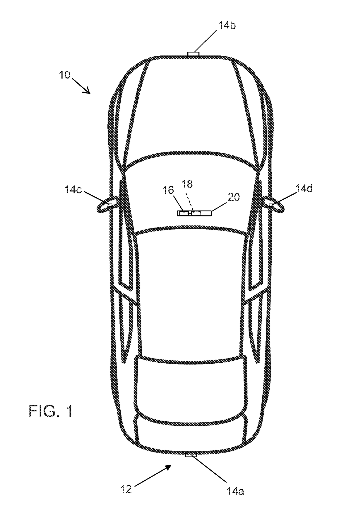
[0020]Referring now to the drawings and the illustrative embodiments depicted therein, a vehicle 10 includes an imaging system or vision system 12 that includes at least one exterior viewing imaging sensor or ca...


PUM


Abstract

A system for testing a camera for vision system for a vehicle includes providing a camera having a field of view and providing and disposing a test structure in the field of view of the camera and between the camera and a target. The test structure includes at least one optic and is capable of directing a principal axis of the at least one optic toward multiple respective regions of the target. The camera views the target via the at least one optic. Image data is captured with the camera. The captured image data is representative of images of the target including the multiple regions of the target as captured when the at least one optic has its principal axis directed toward the respective regions of the target. The image data captured by the camera is processed to determine the focus at each of the multiple regions of the target.

Description

CROSS REFERENCE TO RELATED APPLICATION[0001]The present application claims the filing benefits of U.S. provisional application Ser. No. 62 / 523,961, Jun. 23, 2017, which is hereby incorporated herein by reference in its entirety.FIELD OF THE INVENTION[0002]The present invention relates generally to cameras for a vehicle and, more particularly, to a system for testing focus capabilities of a camera for a vehicle.BACKGROUND OF THE INVENTION[0003]Use of imaging sensors in vehicle imaging systems is common and known. Examples of such known systems are described in U.S. Pat. Nos. 5,949,331; 5,670,935 and / or U.S. Pat. No. 5,550,677, which are hereby incorporated herein by reference in their entireties.[0004]Current testing of cameras (typically far field cameras) requires cameras to be tested at 8 meters or greater to check the focus of a camera at a distance that is representative of how the camera will function in a vehicle during normal driving conditions for the camera to function as d...

Claims


Application Information

Patent Timeline
IPC IPC(8): G06K9/00G06K9/32H04N5/232
CPCG06K9/00805G06K9/3241H04N5/23238H04N5/23229H04N5/23212B60R2001/1253H04N17/002B60R1/00B60R2300/402G02B27/0025G02B27/00G06V20/58H04N23/67H04N23/80H04N23/698
Inventor SESTI, MATTHEW C.OLSON, DAVID F.DEVOTA, ROBERT A.GARCIA, JOHN R.MERSINO, DONALD W.
Owner MAGNA ELECTRONICS
Why Eureka
Try Eureka