Supercharge Your Innovation With Domain-Expert AI Agents!

Double-row bent heat exchanger

a heat exchanger and double-row technology, applied in indirect heat exchangers, heating types, lighting and heating apparatus, etc., can solve the problems of poor heat exchange performance and large waste of space, and achieve the effect of reducing the bending radius of the heat exchanger, reducing the diameter of the header, and effectively utilizing spa

Active Publication Date: 2019-01-10
SANHUA HANGZHOU MICRO CHANNEL HEAT EXCHANGER
View PDF11 Cites 4 Cited by
  • Summary
  • Abstract
  • Description
  • Claims
  • Application Information

AI Technical Summary

Benefits of technology

The technical effects of this patent k text are a double-row bent heat exchanger that reduces the space needed and improves efficiency. This is achieved by reducing the diameter of the header of the heat exchanger and the bending radius, which allows for more heat exchangers to be placed in a limited space.

Problems solved by technology

However, the large flat tube and header will result in a large bending radius, and the large bending radius will cause a great waste of space, such as the space in an air conditioner.
An actual heat-exchange area of the heat exchanger will also be relatively reduced within a constant space, thereby resulting in a poor heat-exchange performance of the heat exchanger.

Method used


Image

  • Double-row bent heat exchanger
  • Double-row bent heat exchanger
  • Double-row bent heat exchanger

Examples


Embodiment Construction

[0026]Embodiments of the present disclosure will be described in detail below, and examples of the embodiments are shown in accompanying drawings. The embodiments described herein with reference to drawings are explanatory, illustrative, and used to generally understand the present disclosure. The embodiments shall not be construed to limit the present disclosure.

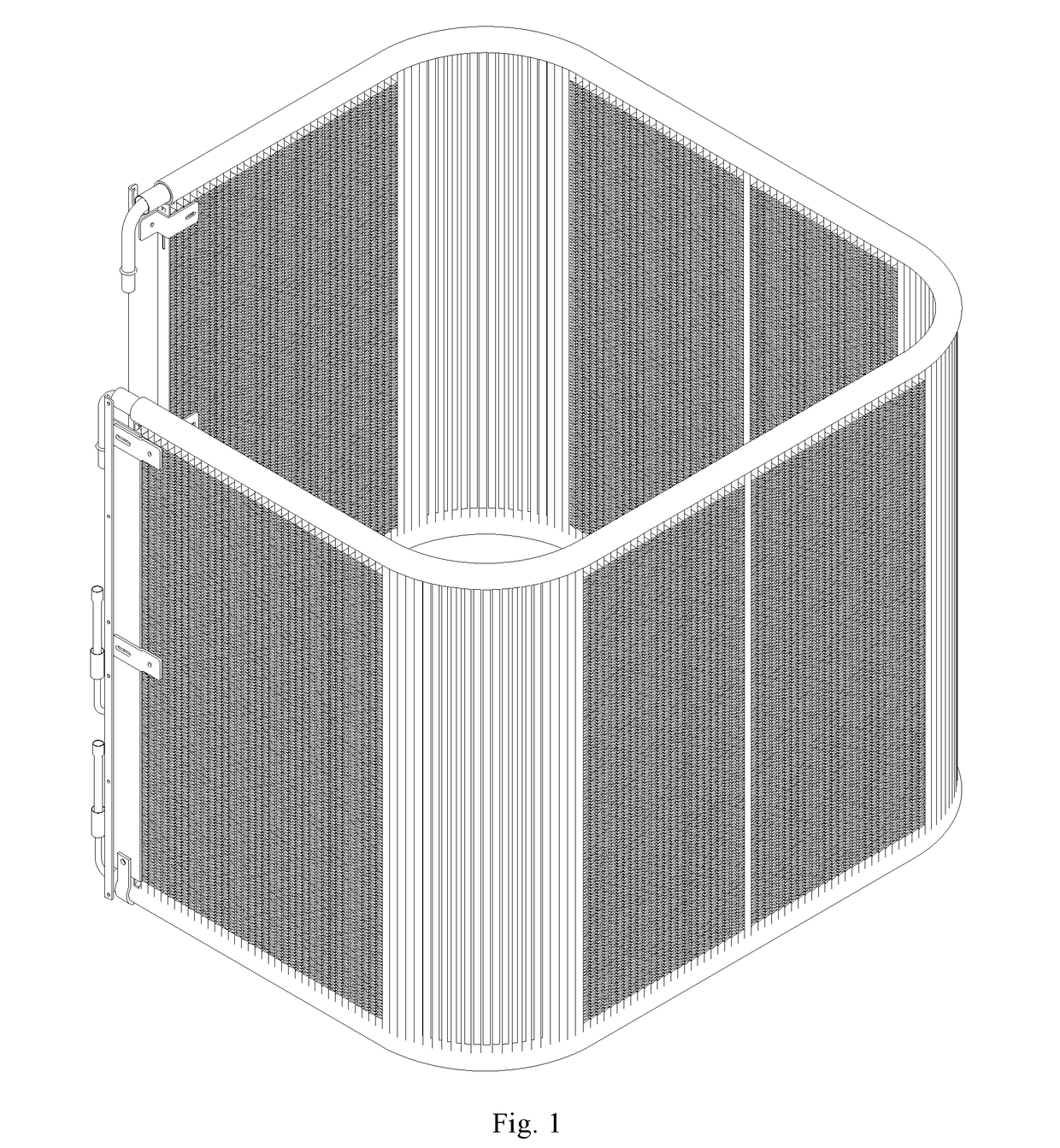
[0027]A double-row bent heat exchanger 1 according to embodiments of the present disclosure will be described with reference to drawings in the following.

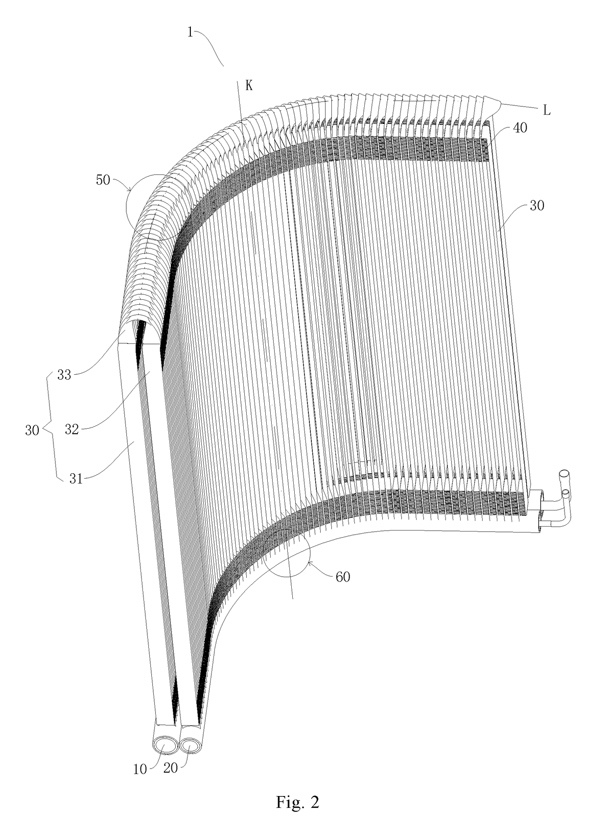
[0028]As illustrated in FIGS. 2 to 7, the heat exchanger 1 according to embodiments of the present disclosure includes a first header 10, a second header 20, flat tubes 30 and fins 40.

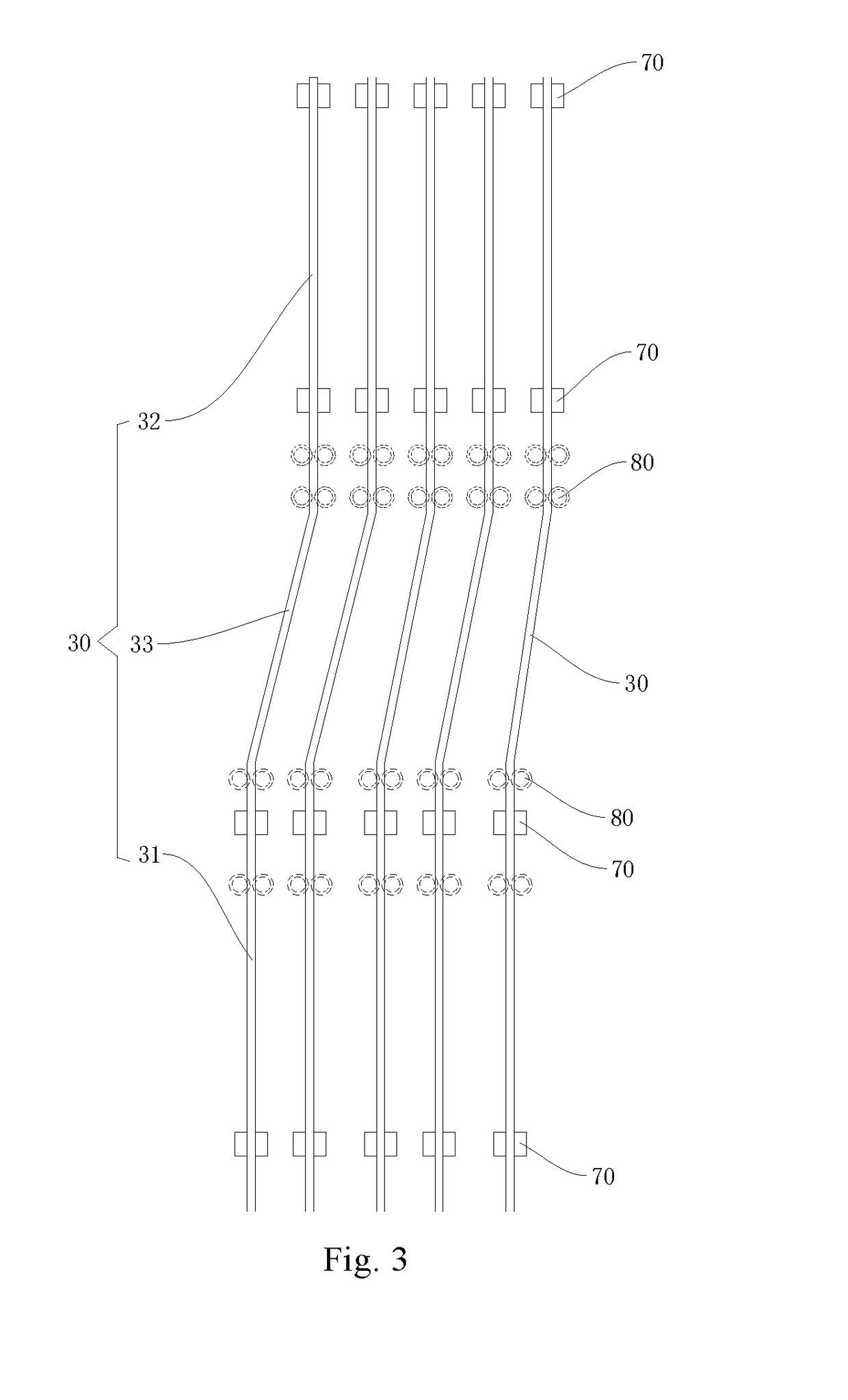
[0029]A length of the second header 20 is less than that of the first header 10. The flat tube 30 is divided into a first straight segment 31, a second straight segment 32 and a twisted segment 33 along a length direction of the flat tube 30. The first straight segment 31 is connected to the ...


PUM


Abstract

A double-row bent heat exchanger is provided. The heat exchanger includes: a first header and a second header; flat tubes each divided into a first straight segment connected to the first header, a second straight segment connected to the second header and a twisted segment connected between the first straight segment and the second straight segment, along a length direction of the flat tube; and fins disposed between adjacent first straight segments and between adjacent second straight segments. The flat tube is bent at the twisted segment around a first bending axis (L) to provide a first bending portion. The first header and the second header are bent around at least one second bending axis (K) to provide at least one second bending portion.

Description

CROSS-REFERENCE TO RELATED APPLICATIONS[0001]The present application is a U.S. National Phase application under 35 USC § 371 of the International Patent Application No. PCT / CN2016 / 108738, filed on Dec. 6, 2016, which claims the benefit of prior Chinese Application No. 201511027379.6, filed with the State Intellectual Property Office of P. R. China on Dec. 30, 2015. The entire contents of the before-mentioned patent applications are incorporated by reference as part of the disclosure of this U.S. application.BACKGROUND OF THE INVENTION1. Field of the Invention[0002]The present disclosure relates to a technical field of heat exchange, and more particularly to a double-row bent heat exchanger.2. Description of the Related Art[0003]In some application scenes, a parallel-flow heat exchanger, such as a micro-channel heat exchanger, needs to be bent around a transverse bending axis (parallel to a length direction of a flat tube) of the heat exchanger (i.e. a header of the heat exchanger is...

Claims


Application Information

Patent Timeline
IPC IPC(8): F28D7/16F28F1/32F28F9/02F28D1/053
CPCF28D7/1684F28F1/32F28F9/0243F28F2210/10F28D1/05391F28F9/0229F28F9/0275F28F9/02F28D1/0476F28D1/05366F28F1/126F28D2001/0273B21D53/085F24F1/18
Inventor HE, YANZHOU, JINGGAO, QIANG
Owner SANHUA HANGZHOU MICRO CHANNEL HEAT EXCHANGER
Features
  • R&D
  • Intellectual Property
  • Life Sciences
  • Materials
  • Tech Scout
  • Unparalleled Data Quality
  • Higher Quality Content
  • 60% Fewer Hallucinations
Learn More