Motion generation method, motion generation device, system, and computer program

a motion generation and robot technology, applied in the field of motion generation methods, can solve problems such as the reduction of work efficiency

Active Publication Date: 2019-01-17
ORMON CORP
View PDF3 Cites 12 Cited by
  • Summary
  • Abstract
  • Description
  • Claims
  • Application Information

AI Technical Summary

Benefits of technology

[0047]According to an aspect, motions for the robot are generated based on not only the information that specifies the first orientation and the second orientation, but also the at least one priority item regarding the movement from the first orientation to the second orientation, thus making it possible to provide the computer program that can generate appropriate motions that give consideration to the input priority item as well.

Problems solved by technology

However, it is not necessarily the case that motions that achieve the shortest movement time are always optimum motions.
For example, if motions that achieve the shortest movement time are generated regardless of the fact that a workpiece is a “right side up” workpiece, problems may occur such as the overturning of the “right side up” workpiece due to not giving consideration to the orientation of the workpiece, and the detachment and scattering of a component not fixed to a gripped workpiece due to not giving consideration to the acceleration applied to the workpiece.
Each time such a problem occurs, the user needs to manually teach optimum motions between control points and regenerate or modify the generated motions, which leads to a decrease in work efficiency.

Method used


Image

  • Motion generation method, motion generation device, system, and computer program
  • Motion generation method, motion generation device, system, and computer program
  • Motion generation method, motion generation device, system, and computer program

Examples


first embodiment

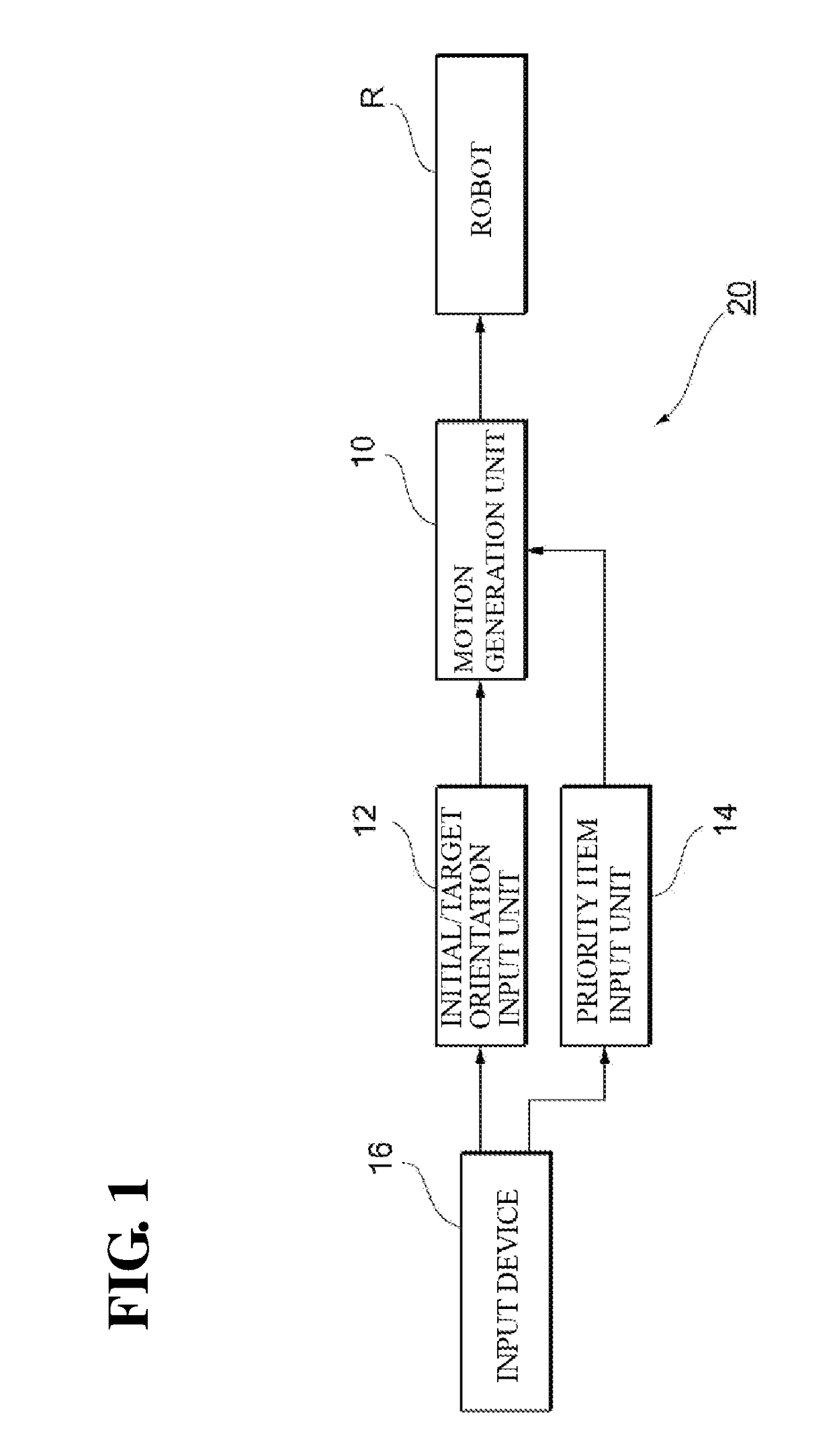
[0064]FIG. 1 is a block diagram showing a motion generation system 20 according to a first embodiment, and this system includes a motion generation unit (motion generation device) 10, an initial / target orientation input unit 12, a priority item input unit 14, an input device 16, and a robot R.

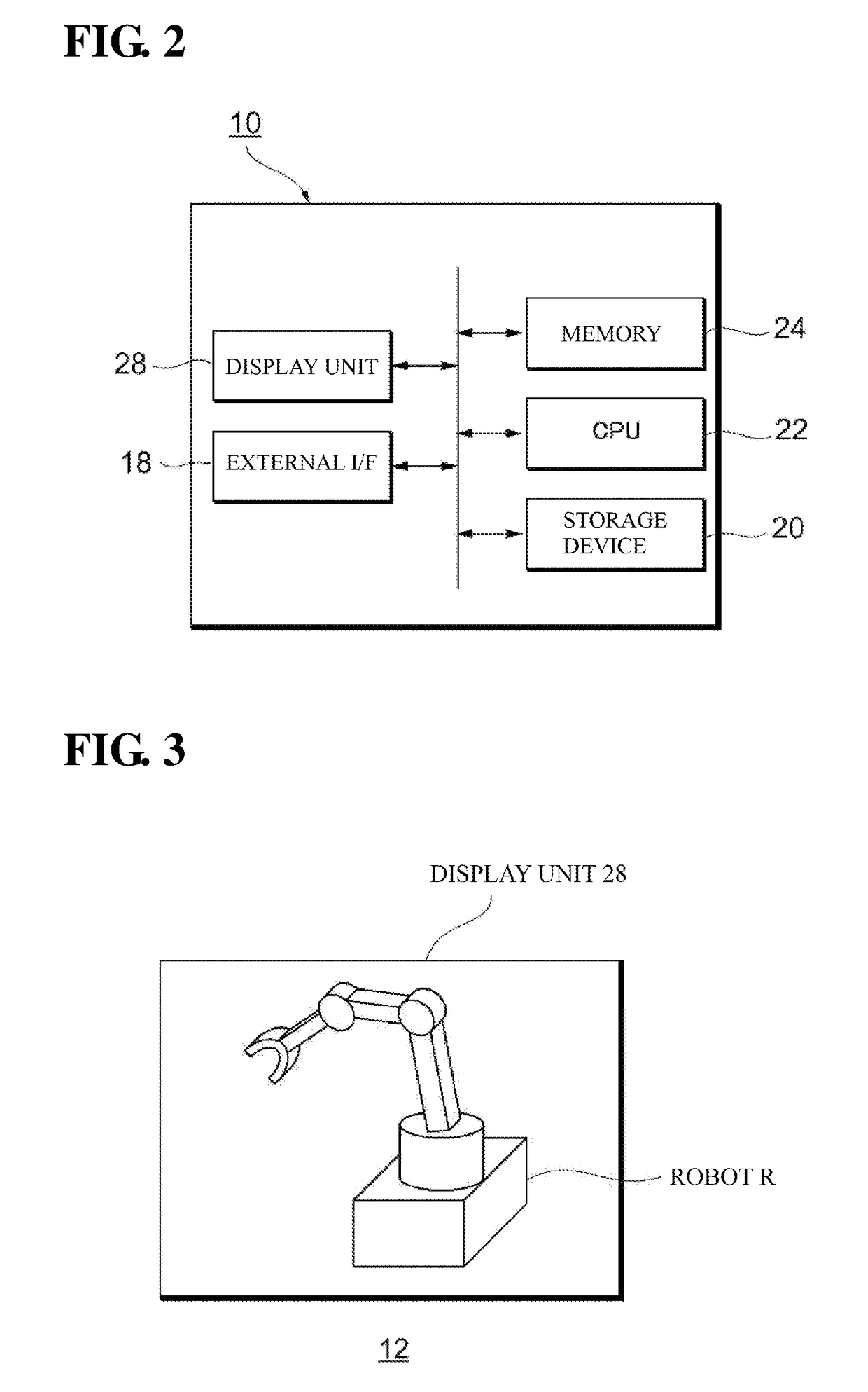
[0065]FIG. 2 shows the internal configuration of the motion generation unit 10. The motion generation unit 10 includes an external I / F 18 (acquisition unit) for exchanging information with an external device, a storage device 20 that stores a computer program for generating motions for the robot R, a CPU 22 for executing the computer program and executing calculation processing for generating motions, and a memory 24 for temporarily storing the computer program and data that is to be processed. The motion generation unit 10 further includes a display unit 28 for displaying data that has been input, processing results, and the like.

[0066]Note that the storage device 20 can be constituted by an H...

second embodiment

[0095]FIG. 7 is a function block diagram showing a motion generation system 40 according to a second embodiment. This motion generation system 40 includes the motion generation unit (motion generation device) 10, the initial / target orientation input unit 12, the input device 16, a priority item input unit 42, an operation-priority item DB 44, and a display device 46. In the following, descriptions are not given for matters that are the same as in a first embodiment, and only differences will be described.

[0096]The motion generation system 40 of an embodiment is different from the motion generation system 20 of a first embodiment with respect to including the operation-priority item DB 44, which is a database in which types of operation content are associated with priority items PI. This DB 44 may be provided in a computer that is different from the motion generation unit 10, or may be provided in the storage device 20 of the motion generation unit 10.

[0097]Also, the display device 4...

third embodiment

[0111]FIG. 9 shows a motion generation system 70 according to a third embodiment.

[0112]This motion generation system 70 includes the initial / target orientation input 12, the priority item input unit 14, the input device 16, and the robot R, as well as a sensor S, a surrounding environment input unit 72, and a motion generation unit 74. Note that in the following, descriptions are not given for matters that are the same as in first and second embodiments, and only differences will be described.

[0113]The motion generation unit 74 includes the external I / F 18 (acquisition unit) for exchanging information with an external device, the storage device 20 that stores a computer program for generating motions for the robot R, the CPU 22 for executing the computer program and executing calculation processing for generating motions, the memory 24 for temporarily storing the computer program and data that is to be processed, and the display unit 28 for displaying data that has been input, proce...


PUM


Abstract

A motion generation device may be for generating a movement for changing the robot from a first orientation to a second orientation, and include a first acquisition unit that acquires first orientation information that specifies the first orientation and second orientation information that specifies the second orientation, a second acquisition unit that acquires at least one priority item regarding the movement for changing from the first orientation to the second orientation, and a movement generation unit that generates a motion of the robot that includes a movement path along which the robot moves from the first orientation to the second orientation, based on the first orientation information, the second orientation information, and the priority item that were acquired.

Description

CROSS-REFERENCES TO RELATED APPLICATIONS[0001]This application claims priority to Japanese Patent Application No. 2017-137963 filed Jul. 14, 2017, the entire contents of which are incorporated herein by reference.FIELD[0002]The disclosure relates to a motion generation method, a motion generation device, a system, and a computer program for generating movements for a robot.BACKGROUND[0003]There is a conventionally known algorithm called path planning for automatically generating robot motions. In general, the path planning algorithm generates motions for achieving the shortest movement time.[0004]JP 2014-180704A discloses a robot picking system in which the smaller a required time T for a gripper to reach a candidate workpiece WC is, the higher the score of an evaluation value Ev is set. In this robot picking system, candidate data is generated for multiple candidate workpieces WC that are picking object candidates, and an object workpiece WO that is to actually being picked is sele...

Claims


Application Information

Patent Timeline
Patent Type & Authority Applications(United States)
IPC IPC(8): B25J9/16
CPCB25J9/1605B25J9/1666B25J9/1664B25J9/1671B25J9/1697G05B2219/39217G05B2219/39357G05B2219/39358G05B2219/39361G05B2219/40073
Inventor KOJIMA, TAKESHINAKASHIMA, AKANEHAYASHI, KENNOSUKEFUJII, HARUKA
Owner ORMON CORP
Why Eureka
Try Eureka