
Method of coding and decoding images, device for coding and decoding images and computer programmes corresponding thereto

Active Publication Date: 2019-01-24
ORANGE SA (FR)
View PDF1 Cites 3 Cited by
  • Summary
  • Abstract
  • Description
  • Claims
  • Application Information

AI Technical Summary

Benefits of technology

The patent aims to reduce the memory used by encoders without affecting the performance of current blocks of video. It also aims to improve the quality of video reconstruction without requiring more memory resources for decoders.

Problems solved by technology

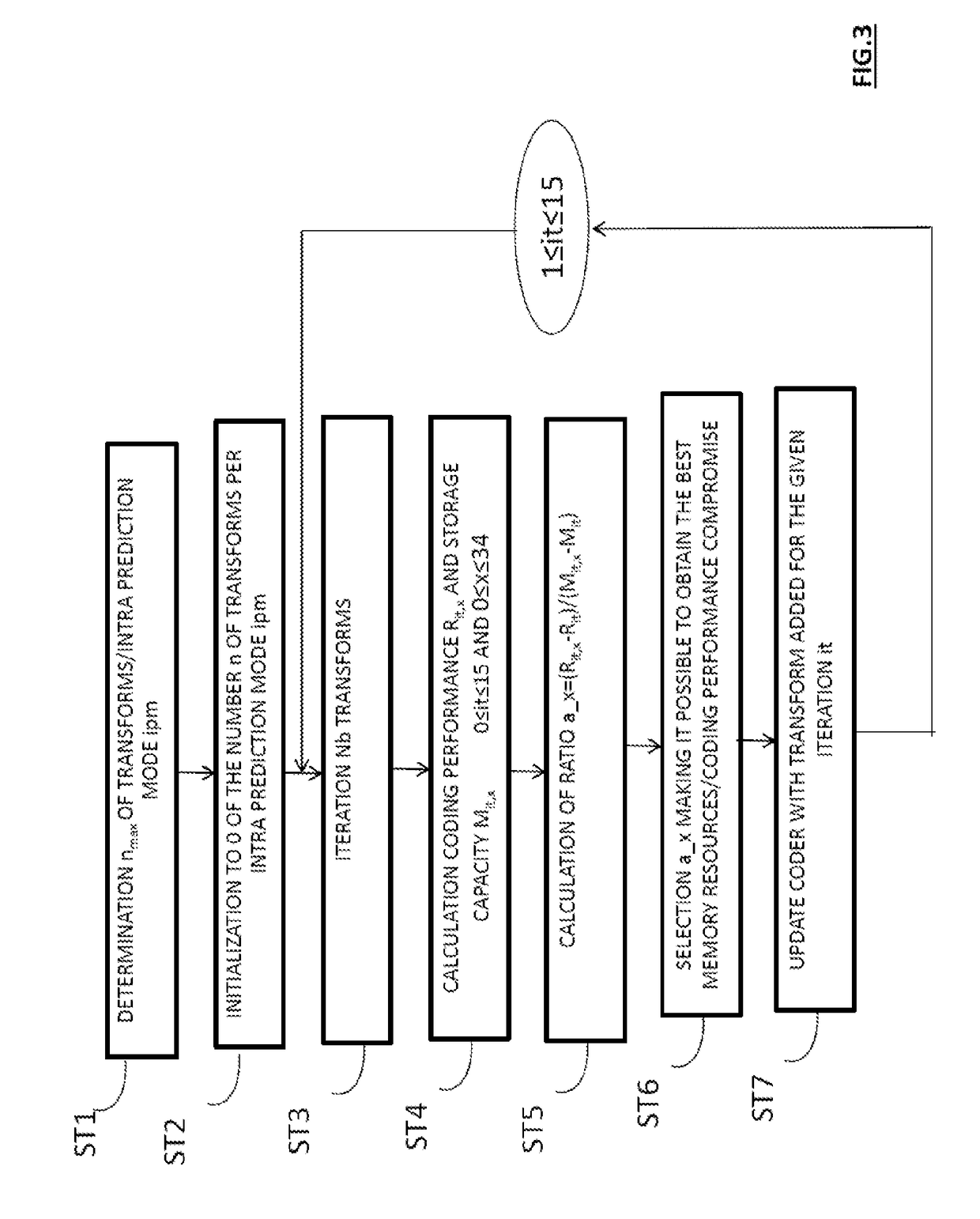
However, such coding performance is not currently optimized and might be further improved, in particular from the point of view of obtaining the best memory resources / coding performance compromise.
Even if the bitrate gain of 2.48% turns out to be beneficial, a memory of capacity 70 kb for storing 560 transforms in order to obtain such a gain turns out to be far too expensive, given that the memories used for the hardware implementation of video coding / decoding systems must be fast as regards the amount of data processed.

Method used


Image

  • Method of coding and decoding images, device for coding and decoding images and computer programmes corresponding thereto
  • Method of coding and decoding images, device for coding and decoding images and computer programmes corresponding thereto
  • Method of coding and decoding images, device for coding and decoding images and computer programmes corresponding thereto

Examples


first embodiment

[0355]In the same manner as on coding, with reference to FIGS. 3 to 8, the decoding method implements, according to the invention, a method for determining the number of transforms for each predetermined mode of prediction, in the case of an HEVC decoding of Intra type.

[0356]An embodiment of the invention implemented in the case of an HEVC decoding of Intra type, and in which the set of transforms which is associated with a mode of intra prediction determined in the course of step D3 of FIG. 11 is stored beforehand in association with at least one other mode of prediction of said plurality of predetermined modes of prediction, will now be described with reference to FIGS. 3, 6A, 6B, 7 to 11.

[0357]In this example, on completion of step D3 of FIG. 11, the optimal predictor block BPopt obtained is associated with an optimal direction of Intra prediction which is for example the direction DPI22.

[0358]In accordance with the present embodiment, the transform (if unique) or the set of tran...

second embodiment

[0376] a type of data displacement is a mirror, inverse to that performed on coding, namely an exchange of the columns or rows of the current decoded modified residual block BDmri. Each datum considered in the current decoded modified residual block BDmri is thus displaced inside the latter, while preserving its closest neighbors.

third embodiment

[0377] a type of data displacement is a combination of the inverse transposition and of the inverse mirror, that is to say:[0378]either the application of a displacement of inverse transposition type followed by the application of a displacement of inverse mirror type to the data of the current decoded modified residual block BDmri,[0379]or the application of a displacement of inverse mirror type followed by the application of a displacement of inverse transposition type to the data of the current decoded modified residual block BDmri.

[0380]Furthermore, according to another embodiment of the invention, the type of data displacement in the current decoded modified residual block BDmri is dependent on the mode of prediction MPs determined in the aforementioned step D3.

[0381]In a manner corresponding to the various types of displacement implemented on coding, such as are represented in FIG. 8, there also exist, on decoding, eight different possible types of displacement numbered from 0...


PUM


Abstract

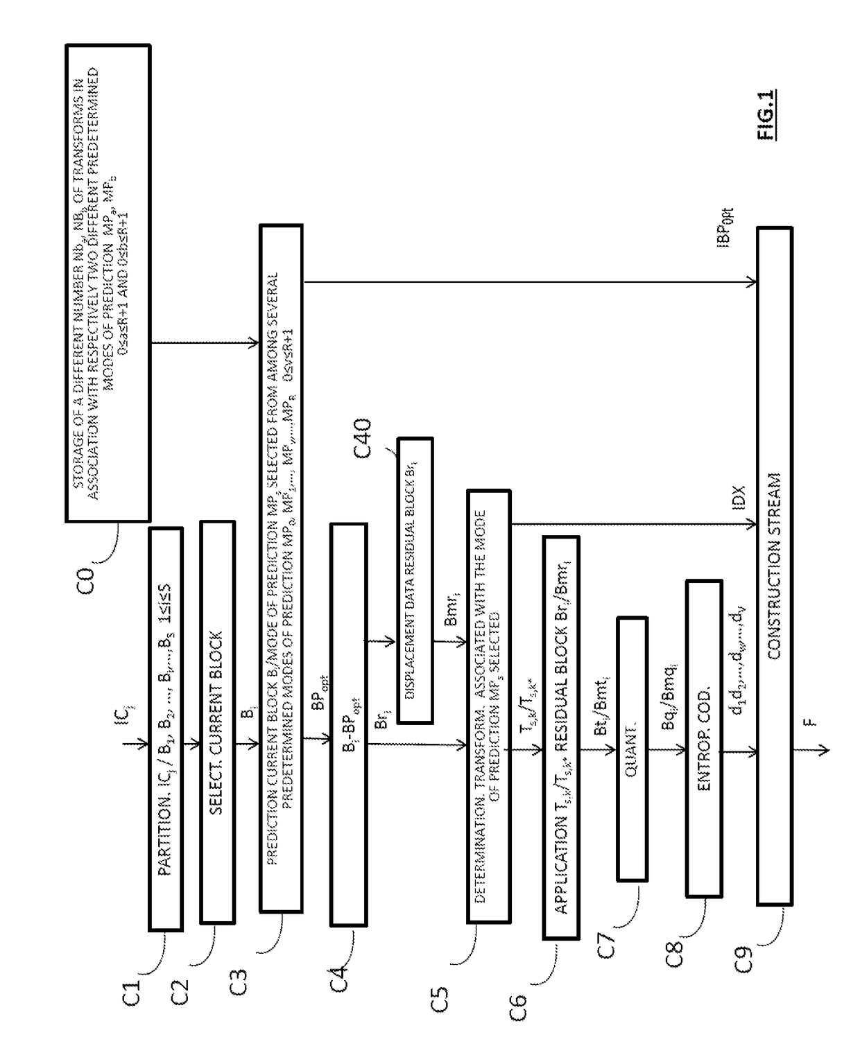
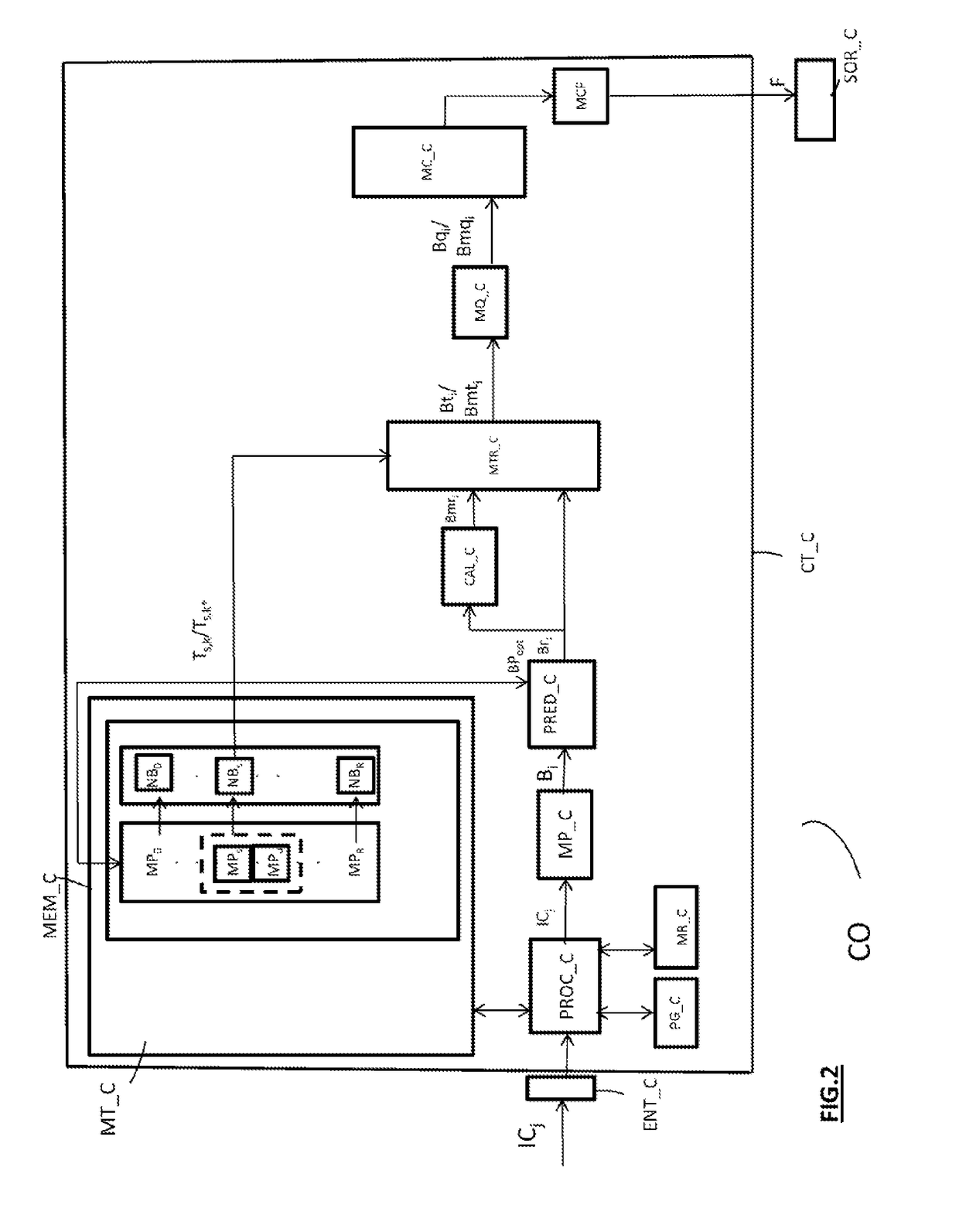
A method of coding at least one image sliced into blocks. The method implements, for a current block to be coded of the image: predicting the current block in accordance with a prediction mode selected from among a plurality of predetermined prediction modes, calculating a residual data block representative of a difference between a predictor block obtained on completion of the prediction and the current block, applying a transform operation to the data of the residual block, the transform operation belonging to a set of transform operations previously stored in association with a selected prediction mode, and coding the data obtained from the transform operation. The number of transform operations contained in the set associated with the selected mode is different from the number of transform operations contained in a set of transform operations stored in association with at least one other predetermined prediction mode of the plurality.

Description

FIELD OF THE INVENTION[0001]The present invention pertains generally to the field of image processing, and more precisely to the coding and to the decoding of digital images and of sequences of digital images.[0002]The coding / decoding of digital images applies in particular to images arising from at least one video sequence comprising:[0003]images arising from one and the same camera and following one another temporally (coding / decoding of 2D type),[0004]images arising from various cameras oriented according to different views (coding / decoding of 3D type),[0005]corresponding components of texture and of depth (coding / decoding of 3D type),[0006]etc.[0007]The present invention applies in a similar manner to the coding / decoding of images of 2D or 3D type.[0008]The invention can in particular, but not exclusively, be applied to the video coding implemented in AVC and HEVC current video coders and their extensions (MVC, 3D-AVC, MV-HEVC, 3D-HEVC, etc.), and to the corresponding decoding.P...

Claims


Application Information

Patent Timeline
IPC IPC(8): H04N19/61H04N19/103H04N19/176
CPCH04N19/61H04N19/103H04N19/176H04N19/12H04N19/157H04N19/105
Inventor PHILIPPE, PIERRICKARRUFAT, ADRIA
Owner ORANGE SA (FR)
Learn More