
Display driving integrated circuit and method for determining wire configuration of the same

Inactive Publication Date: 2007-06-14
SHARP KK
View PDF10 Cites 4 Cited by
  • Summary
  • Abstract
  • Description
  • Claims
  • Application Information

AI Technical Summary

Benefits of technology

[0036] The present invention was made in view of the foregoing problems. An object of the present invention is to provide (i) a display driving integrated circuit capable of surely detecting a foreign matter having a large resistance which gets caught between adjacent reference voltage wires, thereby increasing the quality of the display driving integrated circuit, and (ii) a method for determining a wire configuration of the display driving integrated circuit.
[0038] With the arrangement, the n reference voltage wires are configured so that a potential difference corresponds to two tones or more between adjacent two reference voltage wires. Consequently, a potential difference between adjacent two reference voltage wires is large. Therefore, even if a foreign matter having a large resistance value gets caught between adjacent reference voltage wires, a potential value changed by the foreign matter between the reference voltage wires is larger than a resolution of a tester. Therefore, it is possible to surely detect a foreign matter having a large resistance value which gets caught between adjacent reference voltage wires, so that it is possible to increase the quality of the display driving integrated circuit.
[0040] With the arrangement, the n reference voltage wires provided in parallel, via which the n tone display reference voltages are supplied, are configured so that a potential difference corresponds to two tones or more between adjacent two reference voltage wires. Consequently, a potential difference between adjacent two reference voltage wires is large. Therefore, even if a foreign matter having a large resistance value gets caught between adjacent reference voltage wires, a potential value changed by the foreign matter between the reference voltage wires is larger than a resolution of a tester. Therefore, it is possible to surely detect a foreign matter having a large resistance value which gets caught between adjacent reference voltage wires, so that it is possible to increase the quality of the display driving integrated circuit.

Problems solved by technology

Consequently, a potential difference between adjacent two reference voltage wires is large.

Method used


Image

  • Display driving integrated circuit and method for determining wire configuration of the same
  • Display driving integrated circuit and method for determining wire configuration of the same
  • Display driving integrated circuit and method for determining wire configuration of the same

Examples


Embodiment Construction

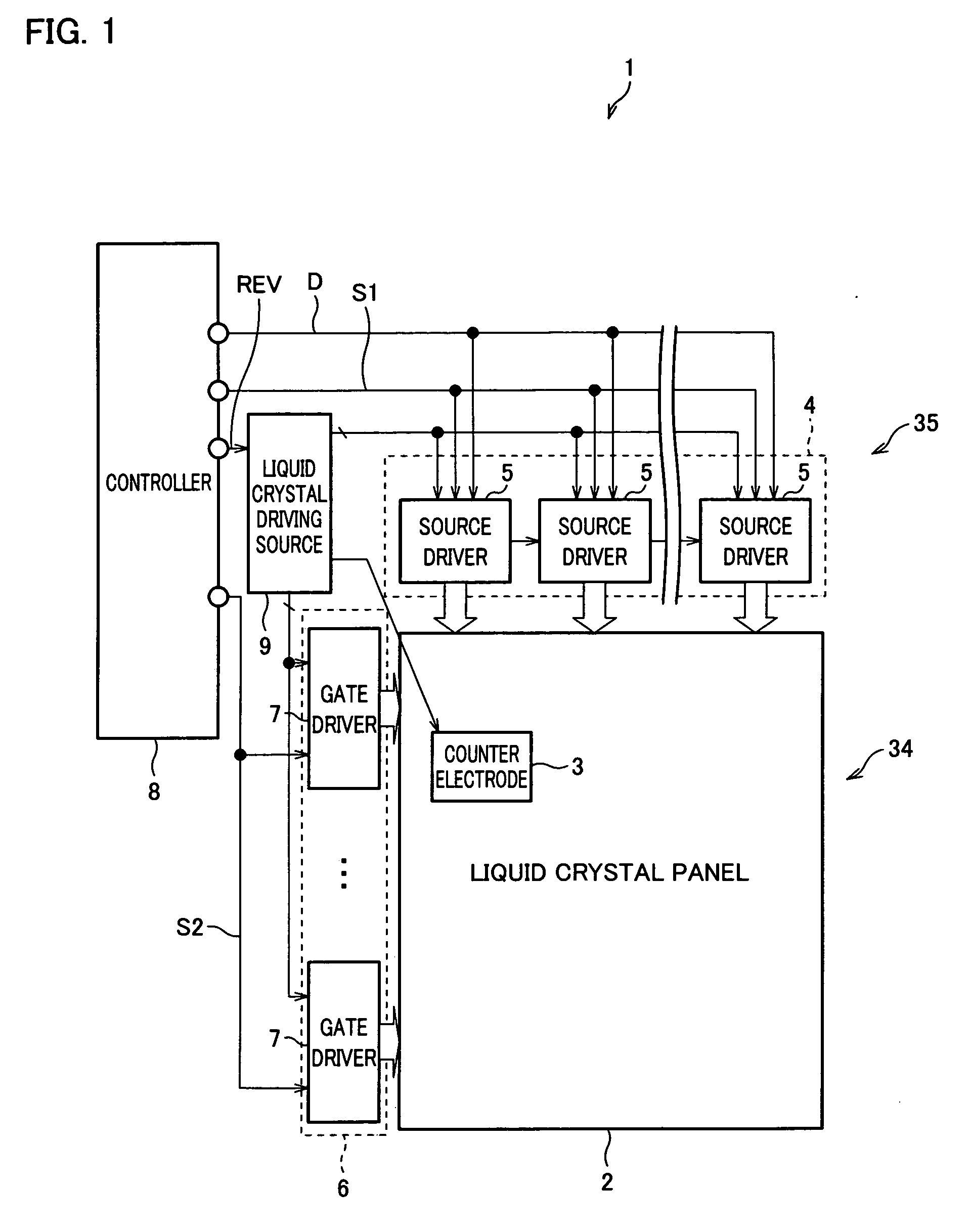
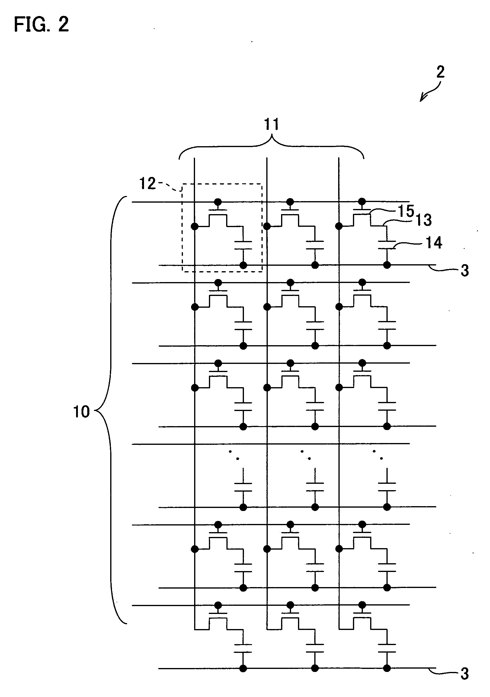
[0068] The following explains an embodiment of the present invention with reference to FIGS. 1 to 12. FIG. 1 is a block diagram illustrating a main structure of a liquid crystal display apparatus 1 in an embodiment of the present invention. FIG. 2 is a circuit diagram illustrating a main structure of a liquid crystal panel 2 included in the liquid crystal display apparatus 1.

[0069] The liquid crystal display apparatus 1 is a TFT (thin film transistor) liquid crystal display apparatus, which is one of typical examples of active matrix liquid crystal display apparatuses. The liquid crystal display apparatus 1 includes a liquid crystal display section 34 and a liquid crystal driving circuit (liquid crystal driving section) 35 for driving the liquid crystal display section 34. The liquid crystal display section 34 includes a liquid crystal panel 2 which is a TFT liquid crystal panel. In the liquid crystal panel 2, liquid crystal display elements 12 (FIG. 2) and counter electrodes (comm...


PUM


Abstract

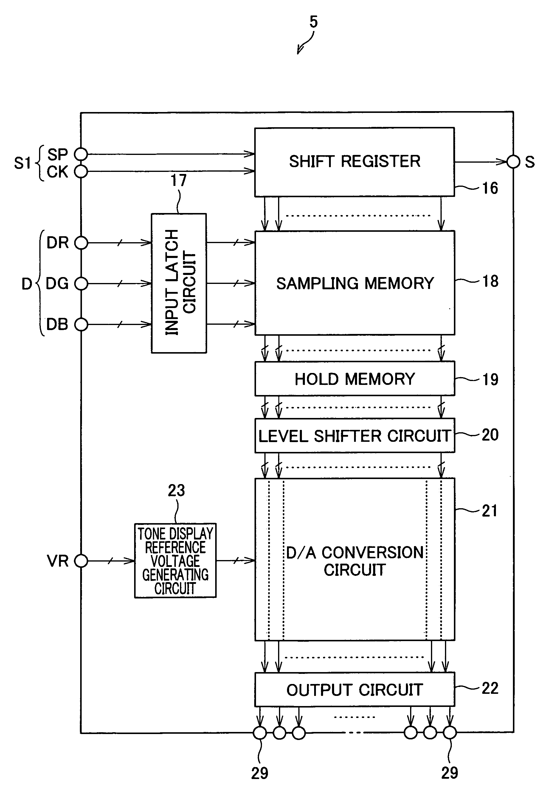
A display driving integrated circuit includes: a tone display reference voltage generating circuit for generating 64 tone display reference voltages by resistive division on the basis of a predetermined reference voltage; D / A conversion circuits each for performing an analog conversion with respect to display data on the basis of the 64 tone display reference voltages; and 64 reference voltage wires provided in parallel, via which the 64 tone display reference voltages are supplied to the D / A conversion circuits, respectively. The 64 reference voltage wires are provided so that a potential difference corresponds to two tones or more between adjacent two reference voltage wires.

Description

[0001] This non-provisional application claims priority under 35 U.S.C. § 119(a) on Patent Application No. 355016 / 2005 filed in Japan on Dec. 8, 2005, and Patent Application No. 284360 / 2006 filed in Japan on Oct. 18, 2006, the entire contents of which are hereby incorporated by reference. FIELD OF THE INVENTION [0002] The present invention relates to (i) a display driving integrated circuit which includes: a tone display reference voltage generating circuit for generating tone display reference voltages corresponding to gray scale levels (referred to as “tone levels” hereinafter); DA conversion circuits each for performing an analog conversion of display data on the basis of the tone display reference voltages; and reference voltage wires for supplying the tone display reference voltages to the DA conversion circuits, and (ii) a method for determining a wire configuration of the display driving integrated circuit. BACKGROUND OF THE INVENTION [0003] In an active matrix liquid crystal...

Claims


Application Information

Patent Timeline
IPC IPC(8): G09G3/36
CPCG09G3/006G09G3/3688G09G3/3696G09G2300/0426G09G2320/02G02F1/133G09G3/20G09G3/36
Inventor KAJIHARA, NORIYUKIFUJINO, HIROAKINAKAO, TOMOAKIORISAKA, YUKIHISAMIYAZAKI, EISAKUNAKAHARA, MICHIHIRONISHIDA, YASUHIROMONOMOHSHI, MASAHIKO
Owner SHARP KK
Learn More