
Driver circuit of display device

Active Publication Date: 2011-09-29
HIMAX TECH LTD
View PDF4 Cites 6 Cited by
  • Summary
  • Abstract
  • Description
  • Claims
  • Application Information

AI Technical Summary

Benefits of technology

[0009]Accordingly, the present invention provides a driver circuit and a display device using the same that saves power consumption by reducing voltage swing of each driving channel thereof and increases display quality by performing dot inversion. In addition, the driver circuit alters data modes of the driving channels at two ends of same data line to be matched for ensuring each driving channel receives signal from correct data path.
[0014]The present invention provides the driver circuit that during different scan periods, each of a plurality of driving channels in the driver circuit respectively can output data driving signals with the same polarity to pixel cells arranged in a zigzag manner interlaced on two neighboring data lines for performing dot inversion. Therefore, each driving channel of the source driver reduces its voltage swing for saving the power consumption, and increasing display quality by performing dot inversion. Additionally, data modes of driving channels at two ends of the same data line in different source drivers are altered to be matched in order to ensure that the driving channels of each source driver can receive video data from the correct data path.

Problems solved by technology

Such kind of the source driver causes more power consumption due to high voltage swings of the data driving signals.
Nevertheless, the display quality of performing the column inversion or the frame inversion is not good as the dot inversion.
As a result, designers have disturbance on trading off between the power consumption and the display quality.
Additionally, when performing polarity inversion, if frequency of switching the positive polarity and the negative polarity is not quick enough, people may perceive flickers on frames easily.
The source drivers may be disposed at different sides of the display panel, e.g. upper side and lower side, due to the limitation of panel layout space.

Method used


Image

  • Driver circuit of display device
  • Driver circuit of display device
  • Driver circuit of display device

Examples


Embodiment Construction

[0022]Reference will now be made in detail to the present preferred embodiments of the invention, examples of which are illustrated in the accompanying drawings. Wherever possible, the same reference numbers are used in the drawings and the description to refer to the same or like parts.

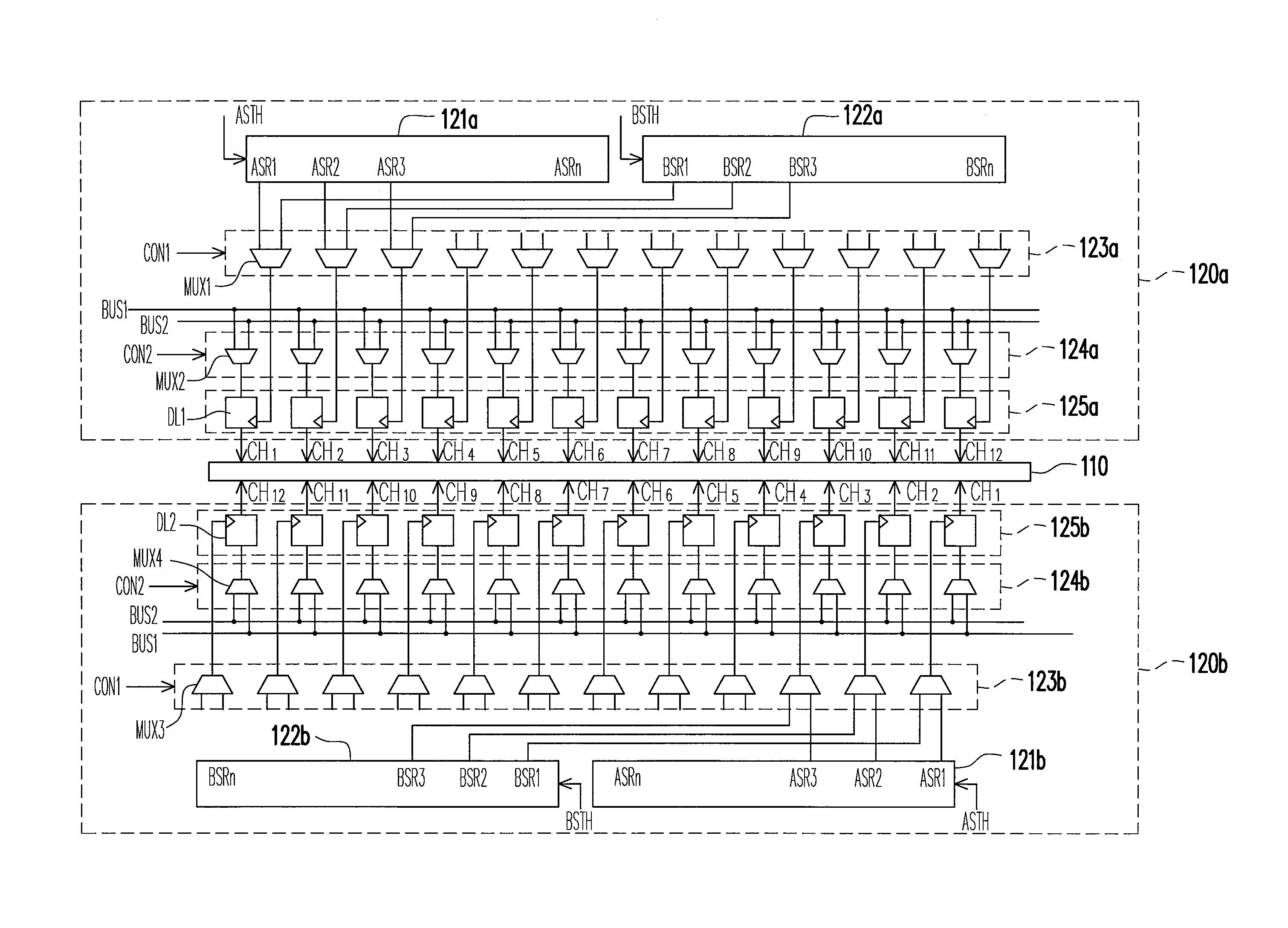
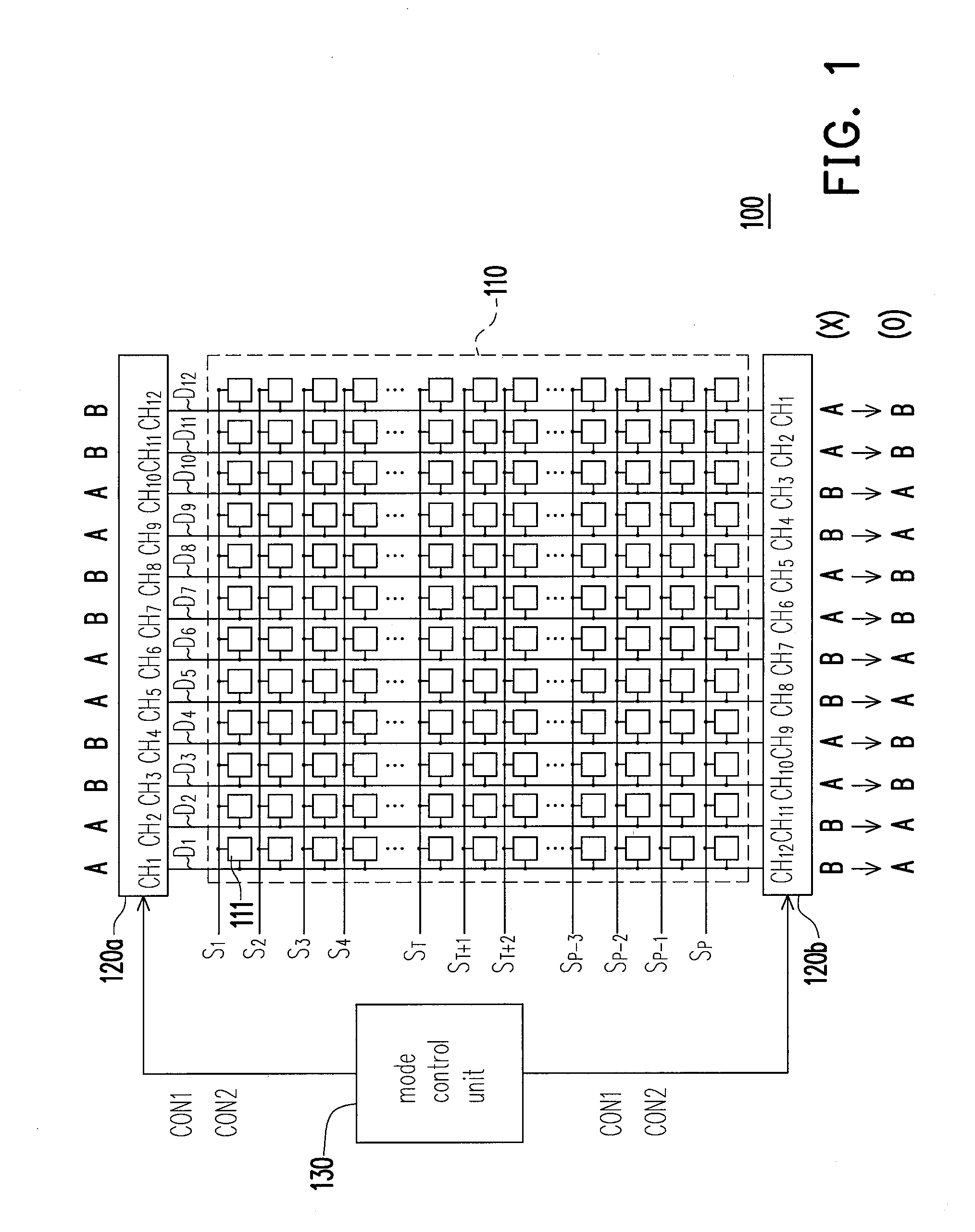
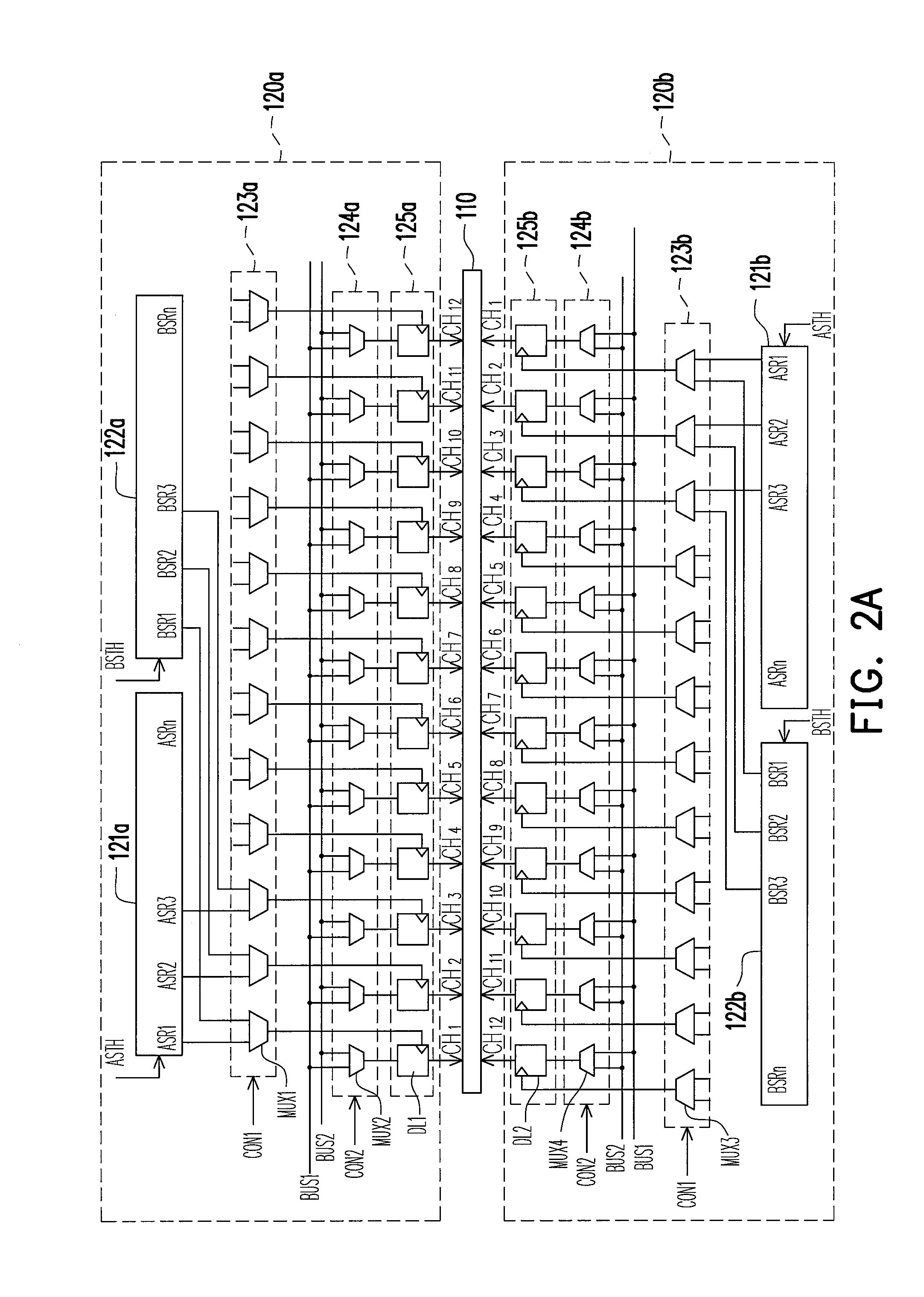
[0023]FIG. 1 is a diagram of a display device according to an embodiment of the present invention. Referring to FIG. 1, the display device 100, such as liquid crystal display (LCD), includes a display panel 110 and a driver circuit for driving a plurality of pixel cells 111 arranged in an array manner on the display panel 110. There are N pixel cells on each of a plurality of scan lines S1-SP, wherein N and P are positive integers, for example, N=12, and the N pixel cells 111 on each scan line respectively coupled to the data lines D1-DN. The driver circuit includes a mode control unit 130 and a plurality of source drivers, e.g., the source drivers 120a and 120b. Each of the source drivers 120a and 1...


PUM


Abstract

A driver circuit includes a mode control unit and a plurality of source drivers to drive a display panel including pixel cells on each scan line. Each source driver has M driving channels, and two subsets of the driving channels are respectively in a first mode and a second mode according to a preset mode sequence. The 1st through Nth driving channels of each of first source drivers and the Mth through (M−N+1)th driving channels of each of second source drivers respectively drive the pixel cells during a first scan period and a second scan period, wherein M≧N. The modes of the Mth through 1st driving channels of the second source drivers are respectively altered to match the modes of the 1st through Mth driving channels of the first source drivers by the mode control unit.

Description

BACKGROUND OF THE INVENTION [0001]1. Field of the Invention[0002]The present invention generally relates to a driver circuit, and more particularly to a driver circuit for reducing power consumption of the display device.[0003]2. Description of Related Art[0004]A liquid crystal display (LCD) includes a timing controller, a display panel, a plurality of gate drivers, and a plurality of source drivers. The display panel includes a plurality of pixel cells arranged in an array, and each pixel cell is coupled to one of a plurality of scan lines and one of a plurality of data lines. The timing controller outputs video data to the source drivers for converting the video data into data driving signals. In addition, the timing controller controls each gate driver to sequentially enable the scan lines, and then controls each source driver to deliver data driving signals to the pixel cells on the enabled scan line via the data liens so as to display a frame.[0005]Generally, the polarities of ...

Claims


Application Information

Patent Timeline
IPC IPC(8): H03K3/00
CPCG09G3/3614G09G3/3688G09G2330/021G09G2310/0297G09G2320/0252G09G2310/0281
Inventor WENG, MENG-TSE
Owner HIMAX TECH LTD
Learn More