[0031]wherein: 1—vacuum cleaner body;
[0032]2—dust suction head;
[0033]3—dust suction tube (conductive telescopic tube); 30—sleeving; 30a—first tube body; 30b—second tube body; 31—conductive assembly; 310—mounting seat; 310a—first mounting seat; 310b—second mounting seat; 311—contact strip; 311a—conductive sheet; 311b—first contact strip; 311c—second contact strip; 312—conductive joint; 313—elastic sheet; 32—locking mechanism; 320—locking element; 320a—locking seat; 320b—locking pin; 321—locked portion; 321a—recess; 321b—locking bar; 322—unlocking element; 322a—unlocking button; 322b—restoring member (elastic);
[0034]4—connector;
[0035]5—conductive plug connector;
[0036]a—mounting groove; b—locking groove.
DETAILED DESCRIPTION OF EXEMPLARY EMBODIMENTS
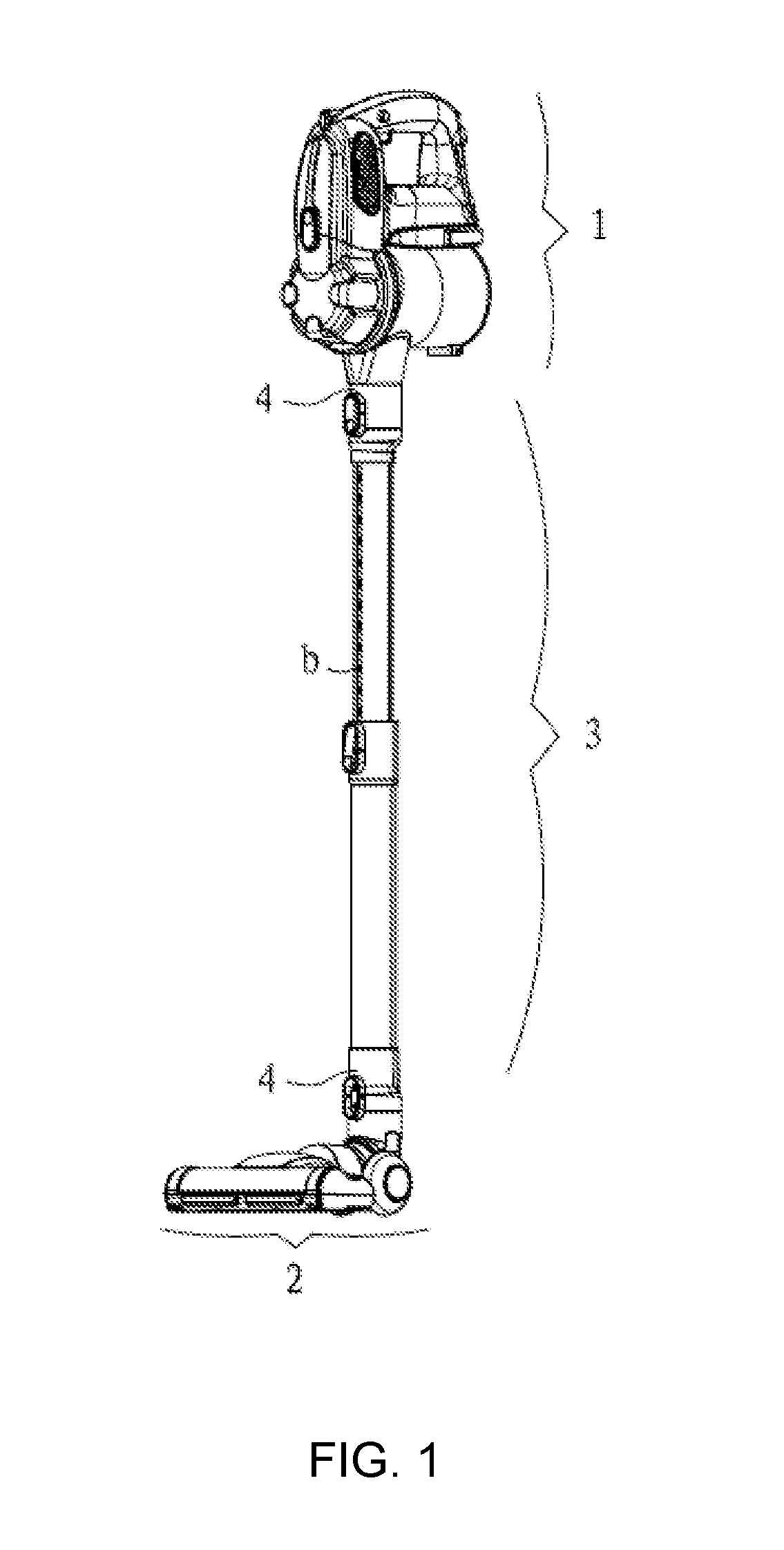
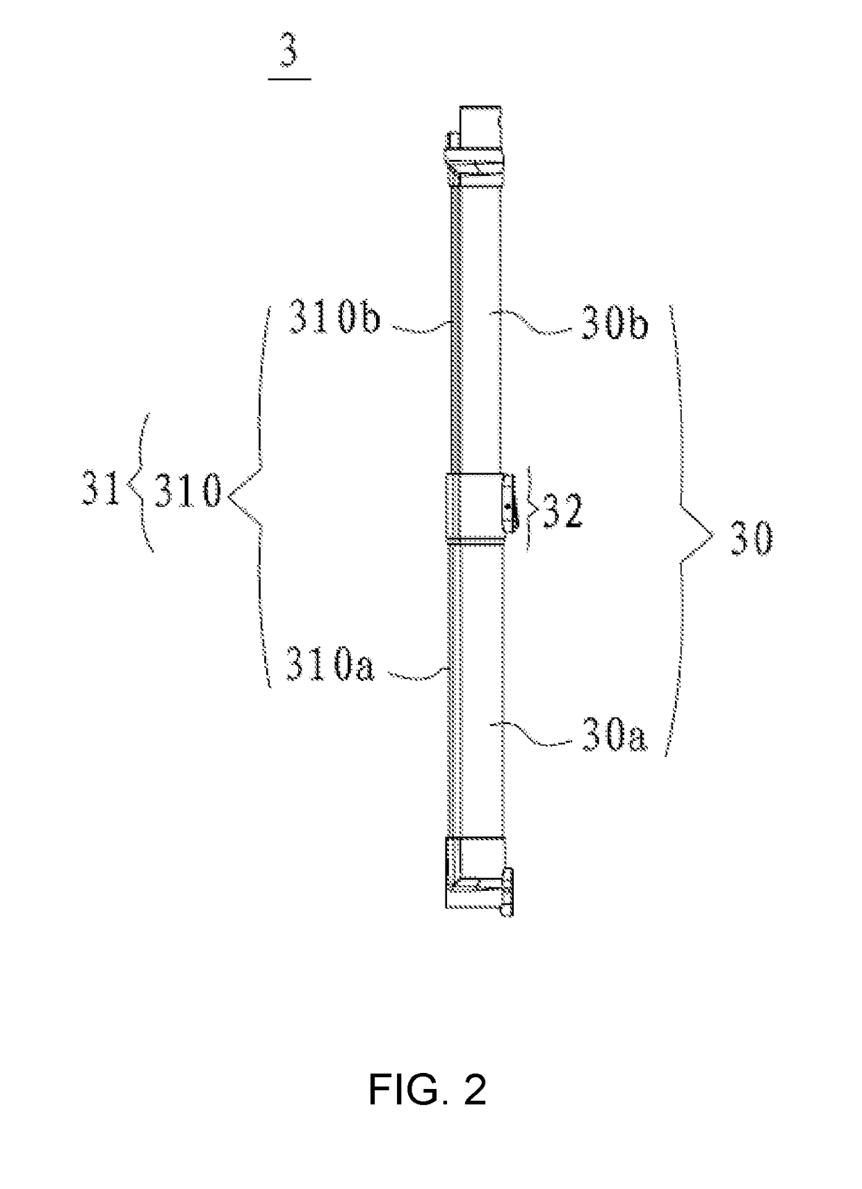
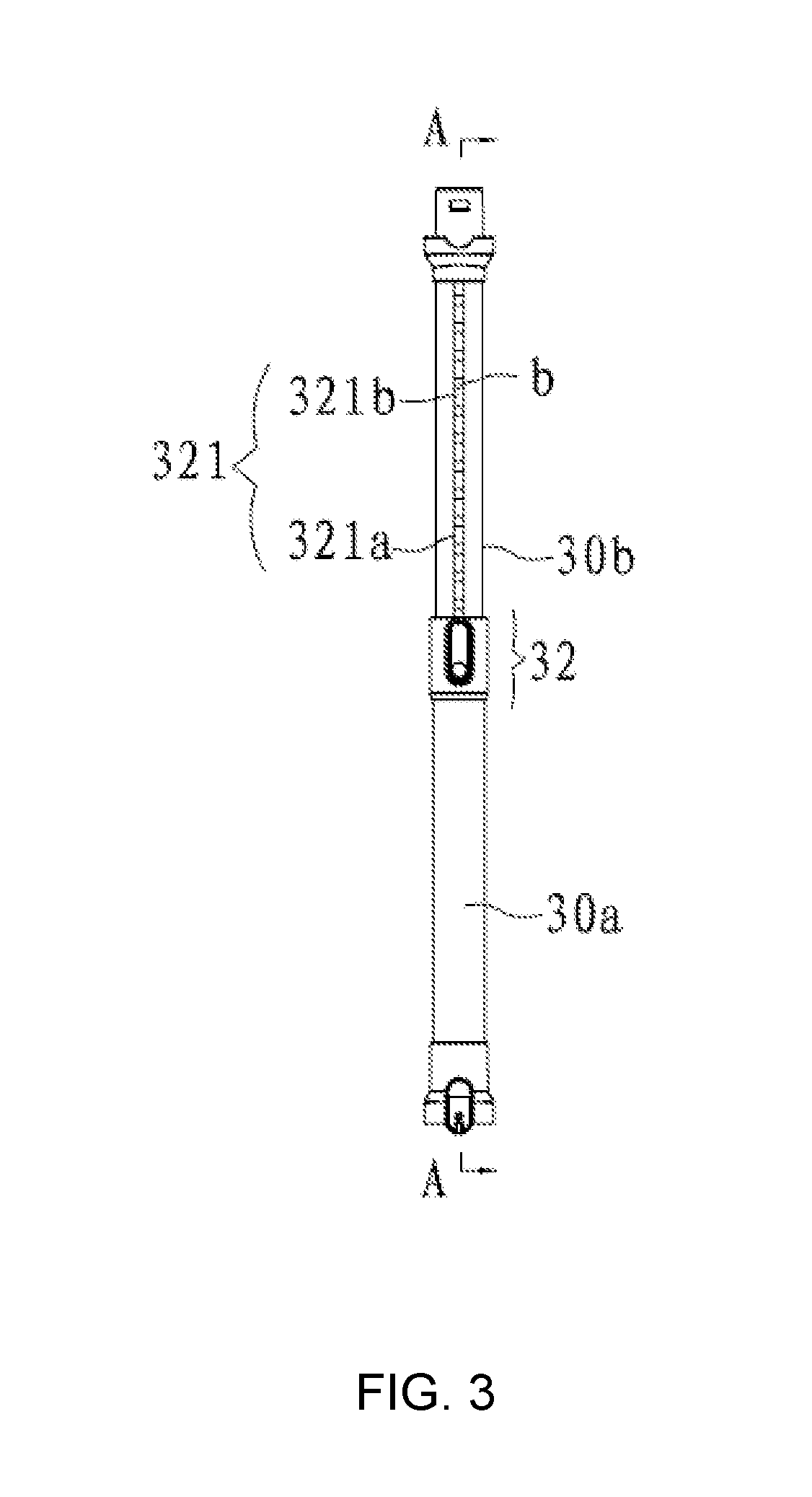
[0037]As shown in FIG. 1 to FIG. 9, a hand-held vacuum cleaner provided by the present embodiment includes s a vacuum cleaner body 1, a dust suction head 2 and a dust suction tube 3, wherein the dust suction tube 3 is a conductive telescopic tube, and two end portions thereof are connected with the vacuum cleaner body 1 and the dust suction head 2 respectively.
[0038]In particular, the above-mentioned hand-held vacuum cleaner further includes connectors 4 disposed at the two end portions of the conductive telescopic tube 3 respectively and being connected with the vacuum cleaner body 1 and the dust suction head 2 by way of clamping respectively, and conductive plug connectors 5 disposed within the connector 4 respectively, wherein the conductive plug connectors 5 are linked with circuits of the vacuum cleaner body 1 and the dust suction head 2 respectively when the conductive telescopic tube 3 is connected with the vacuum cleaner body 1 and the dust suction head 2 in a clamping manner respectively.
[0039]Further, the conductive and telescopic tube 3 includes a plurality of sleevings 30 capable of telescoping in a relative manner, and conductive assemblies 31 disposed on each sleeving 30 and capable of being connected with each other, and the conductive assemblies 31 include a mounting seat 310 disposed on one side of a sleeving 30 along a length direction of each sleeving 30, a contact strip 311 disposed along a length direction of the mounting seat 310, and a conductive joint 312 conductively connecting each of two adjacent contact strips 311 respectively, wherein each of two adjacent mounting seats 310 is telescopically disposed, two end portions of the conductive joint 312 are respectively located within two adjacent mounting seats 310, and capable of always conductively connecting two adjacent contact strips 311 along with a telescopic movement of the two adjacent mounting seats 310.
[0040]In the example, mounting grooves a are disposed on two sides of each mounting seat 310 along its own length direction, the contact strip 311 includes two conductive sheets 311a disposed within the mounting grooves, respectively, and the two end portions of the conductive joint 312 are connected with two conductive sheets 311a of adjacent two contact strips 311, respectively.
[0041]Further, two conductive sheets 311a are disposed in parallel, and are a positive conductive sheet and a negative conductive sheet, respectively, and end portions of the conductive joint 312 are located between the positive conductive sheet and the negative conductive sheet to connect the positive conductive sheet and the negative conductive sheet.
[0042]Two adjacent mounting seats 310 are a first mounting seat 310a and a second mounting seat 310b, respectively, two adjacent contact strips 311 are a first contact strip 311b and a second contact strip 311c, respectively, one end portion of the conductive joint 312 is disposed within the second mounting seat 310b and conductively connected with the positive conductive sheet and the negative conductive sheet of the second contact strip 311c, and the other end portion thereof is inserted into the first mounting seat 310b and conductively connected with the positive conductive sheet and the negative conductive sheet of the first contact strip 311b, the other end portion of the conductive joint 312 and the first contact strip 311b move with respect to each other and keep in contact with each other when the first mounting seat 310a and the second mounting seat 310b are relatively telescopic.
[0043]In particular, the conductive assemblies 31 further includes an elastic sheet 313 disposed on the other end portion of the conductive joint 312 and tending to outstretch, two sides of the elastic sheet 313 press against the positive conductive sheet and the negative conductive sheet of the first contact strip 311b respectively, and conductively connect the positive conductive sheet and the negative conductive sheet of the first contact strip 311b.
[0044]Meanwhile, the conductive and telescopic tube 3 further includes a locking mechanism 32 for locking two sleevings 30 after being adjusted to telescope in a relative manner.
[0045]Two adjacent sleevings 30 are a first tube body 30a and a second tube body 30b, and the locking mechanism 32 includes a locking element 320 disposed on the first tube body 30a, a locked portion 321 disposed on the second tube body 30b and an unlocking element 322, wherein the locking element 320 is locked with the locked portion 321 when the locking mechanism 32 is locked; the locking element 320 is separated from the locked portion 321 when the locking mechanism 32 is unlocked.
[0046]Further, the locked portion 321 includes a recess 321a formed inwardly from a surface of the second tube body 30b and a locking bar 321b disposed within the recess 321a, wherein the recess 321a and the locking bar 321b both extend along a length direction of the second tube body 30b, and the locking bar 321b is provided with a plurality of locking grooves b spaced apart along a length direction of the locking bar 321b.
[0047]More further, the locking member 320 includes a locking seat 320a fixed at an end of the first tube body 30a and a locking pin 320b movably disposed in the locking seat 320a, and the unlocking member 322 includes an unlocking button 322a rotationally disposed in the locking seat 320a by a middle portion and a restoring member 322b disposed between the unlocking button 322a and the locking seat 320a to restore the unlocking button 322a, wherein the locking pin 320b and the restoring member are respectively located at two ends of the unlocking button 322a, and the restoring member 322b is compressed and deformed and the locking pin 320b moves outside the locking seat 320a and disengaged from the locking grooves b to achieve unlocking when the unlocking button 322a is pressed; the restoring member 322b recovers from deformation and the locking pin 320b moves towards inside the locking seat 320a and is inserted into the locking groove b to achieve locking when the unlocking button 322a is released.
[0048]In the present embodiment, the material of the elastic sheets 313, the positive conductive sheets and the negative conductive sheets is copper.
[0049]Above all, the present embodiment has the following advantages:
[0050]1) The whole dust suction tube is turned into a telescopic type, thereby is convenient to carry, and also reduces the volume of the package for sale, leaves a good impression to the consumer.
[0051]2) A unique locking mechanism is employed to lock two telescopic first and second tube bodies with respect to each other, the restoring member is compressed and deformed and the locking pin moves outside the locking seat and disengaged from the locking grooves to achieve unlocking when the unlocking button is pressed; the restoring member recovers from deformation and the locking pin moves towards inside the locking seat and is inserted into the locking groove to achieve automatic locking when the unlocking button is released. The entire process is easy to operate, convenient to implement, and has a low cost.
[0052]3) Due to the external arrangement of the conductive component as well as the ability of telescopic movement along with the conductive and telescopic tube, the adjacent two contact strips are always electrically connected, the structure is simple, the design is ingenious, and the maintenance and replacement are convenient.
[0053]4) The elastic sheets stretching out with respect to each other are employed, so as to connect the positive conductive sheet and the negative conductive sheet constantly, and poor contact or disconnection is less likely to occur, to ensure the safety use of the vacuum cleaner.
[0054]The above detailed describes the present disclosure, and is intended to make those skilled in the art being able to understand the present disclosure and thereby implement it, and should not be concluded to limit the protective scope of this disclosure. Any equivalent variations or modifications according to the spirit of the present disclosure should be covered by the protective scope of the present disclosure.