Front Push Tap

a push tap and push tap technology, applied in the direction of liquid dispensing, liquid flow controller, packaging, etc., can solve the problems that the known types of fluid dispensers can suffer from a variety of problems, and achieve the effect of good sealing and convenient us

Active Publication Date: 2019-01-31
LIQUI BOX
View PDF5 Cites 5 Cited by
  • Summary
  • Abstract
  • Description
  • Claims
  • Application Information

AI Technical Summary

Benefits of technology

[0016]An advantage provided by the disclosed embodiments is that the front push tap spring button is positioned forward of the dispensing port, which makes the tap easier to use.
[0017]The spring button has a bottom edge which has a shape selected from the group consisting of circular, oval, square, rectangular, hexagonal, octagonal, or in the shape of any other suitable polygon. The bottom edge of the spring button can also be thicker to assist in providing a good seal to the tap body.

Problems solved by technology

Known types of fluid dispensers can suffer from a variety of problems: dripping after closure is an example of a problem, as is venting outside air into the container to permit better fluid flow.

Method used


Image

  • Front Push Tap
  • Front Push Tap
  • Front Push Tap

Examples


Embodiment Construction

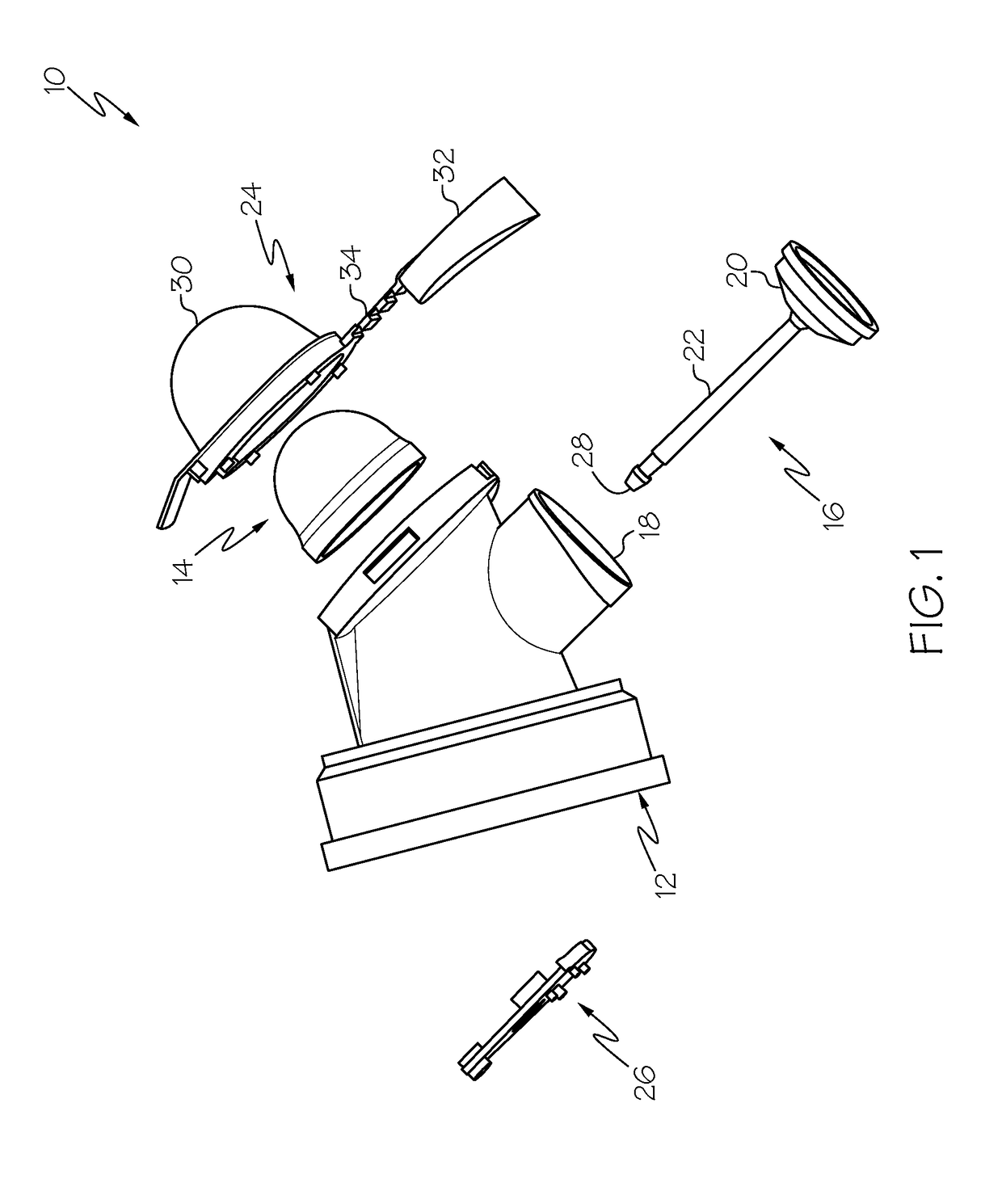
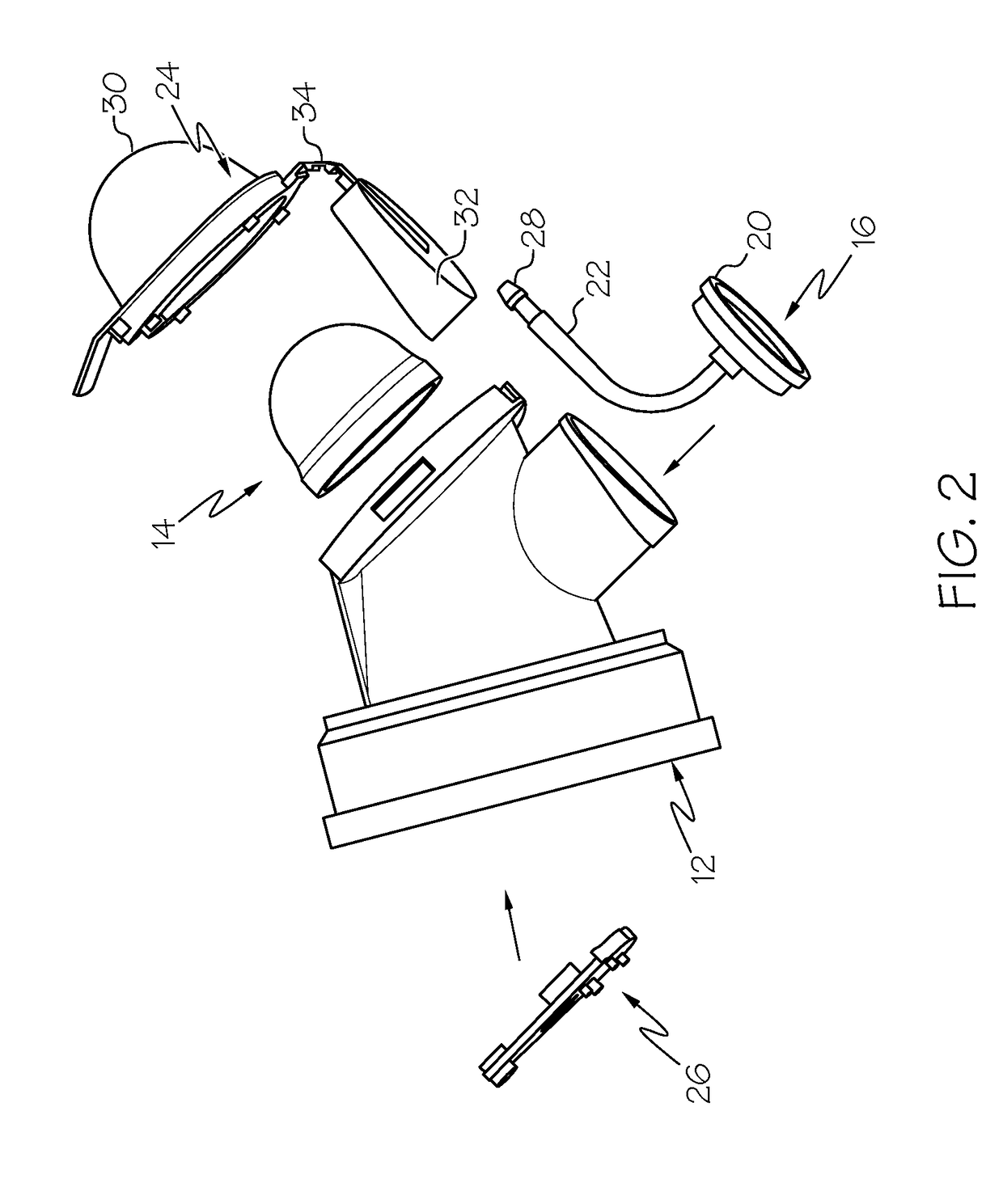
[0030]Referring to FIG. 1, an exploded view showing the parts of a vented embodiment of the front push tap dispenser is shown generally at 10. The tap body is shown at 12, and is a molded plastic part made of ethylene or propylene. The spring button is made from a thermoplastic elastomer and is designed to elastically spring back to its unpressed position after being pressed and released. A valve member is shown at 16 and is comprised of a flexible stem 22 and a seal member 20, which is designed and sized to frictionally seal to an inner wall of the dispenser spout 18. As will be shown in more detail later, the flexible stem 22 attaches to the spring button 14 and when the spring button 14 is in its normal unpressed position, the seal member 20 sealingly fits inside the dispenser spout 18, preventing the flow of liquid. When the spring button 14 is pressed, it causes the flexible stem 22 to move downwardly, causing the seal 20 to move out of contact with the inner wall of the dispen...


PUM


Abstract

A front push tap dispenser has a flow configuration and a sealed configuration. The tap comprises a tap body, a spring button member and a valve seal member, with the two members connected by a flexible stem having two ends, each end connected to the spring button member and the valve seal member. When in the sealed configuration the spring button holds the flexible stem and the valve seal member so the valve seal member is sealingly engaged to the inner wall of the dispensing port. When in the flow configuration the spring button is depressed, which causes the flexible stem and the valve seal to move downwardly to unseal the dispensing port to allow fluid to be dispensed. When the spring button is released, it elastically springs back to the undepressed position, causing the valve seal member to sealingly engage with the inner wall of the dispensing port.

Description

CROSS-REFERENCE TO RELATED APPLICATIONS[0001]This Application claims the benefit of and priority to U.S. Provisional Application No. 62 / 538,119, filed Jul. 28, 2017, the entire contents of which are herein incorporated by reference.STATEMENT REGARDING FEDERALLY SPONSORED RESEARCH[0002]Not Applicable.BACKGROUND OF THE INVENTION[0003]Heretofore, various types of fluid dispensers have been developed to dispense fluid from various types of containers. Known types of fluid dispensers can suffer from a variety of problems: dripping after closure is an example of a problem, as is venting outside air into the container to permit better fluid flow.[0004]Consequently, there remains a need for a fluid dispenser that does not drip after closure and / or is vented to outside air to permit better fluid flow.[0005]Without limiting the scope of the invention a brief summary of some of the claimed embodiments of the invention is set forth below. Additional details of the summarized embodiments of the ...

Claims


Application Information

Patent Timeline
Patent Type & Authority Applications(United States)
IPC IPC(8): B67D3/00
CPCB67D3/0058B67D3/046B67D3/045
Inventor TRETTIN, BRADLEY L.KIERAS, RONALD E.
Owner LIQUI BOX
Why Eureka
Try Eureka