

Light strip system with an elongate carrier rail
- Summary
- Abstract
- Description
- Claims
- Application Information
AI Technical Summary
Benefits of technology
Problems solved by technology
Method used
Image

Examples
Embodiment Construction
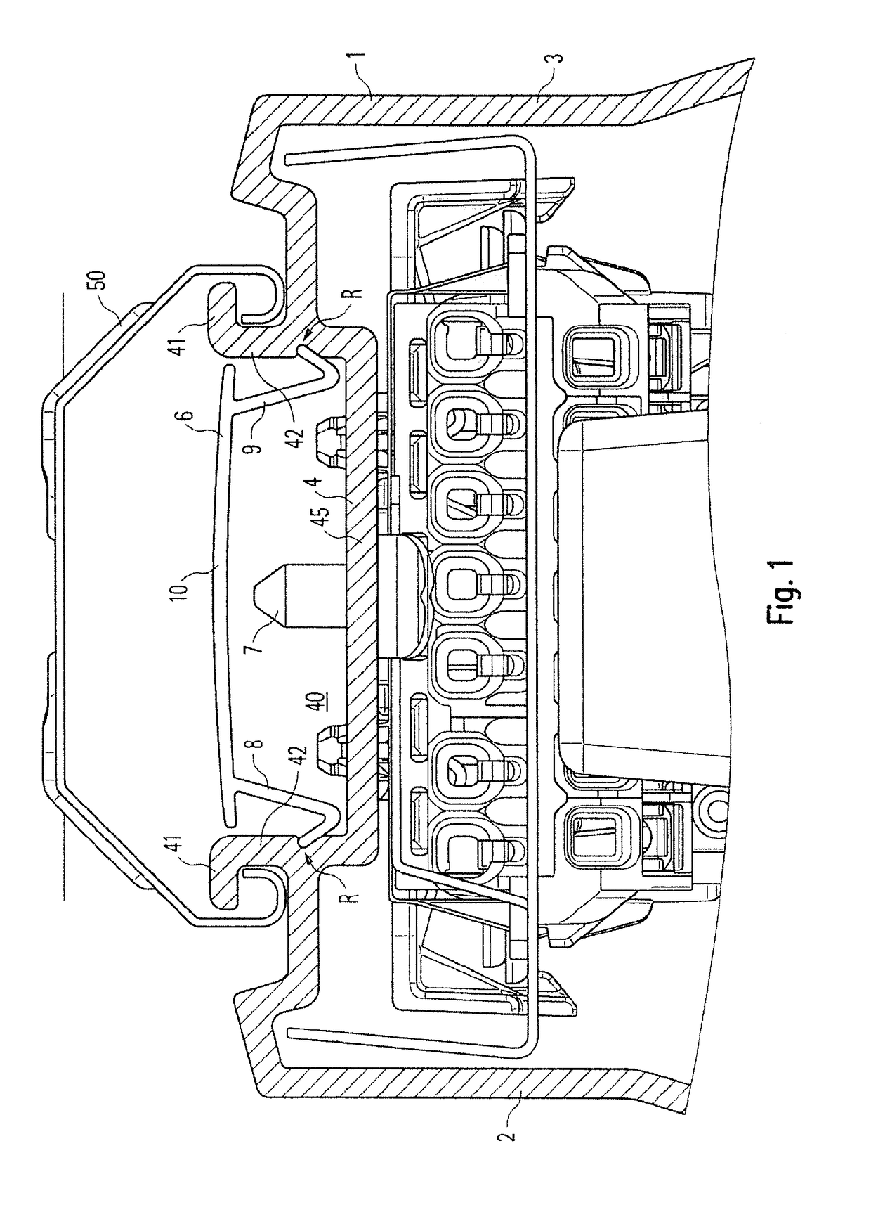
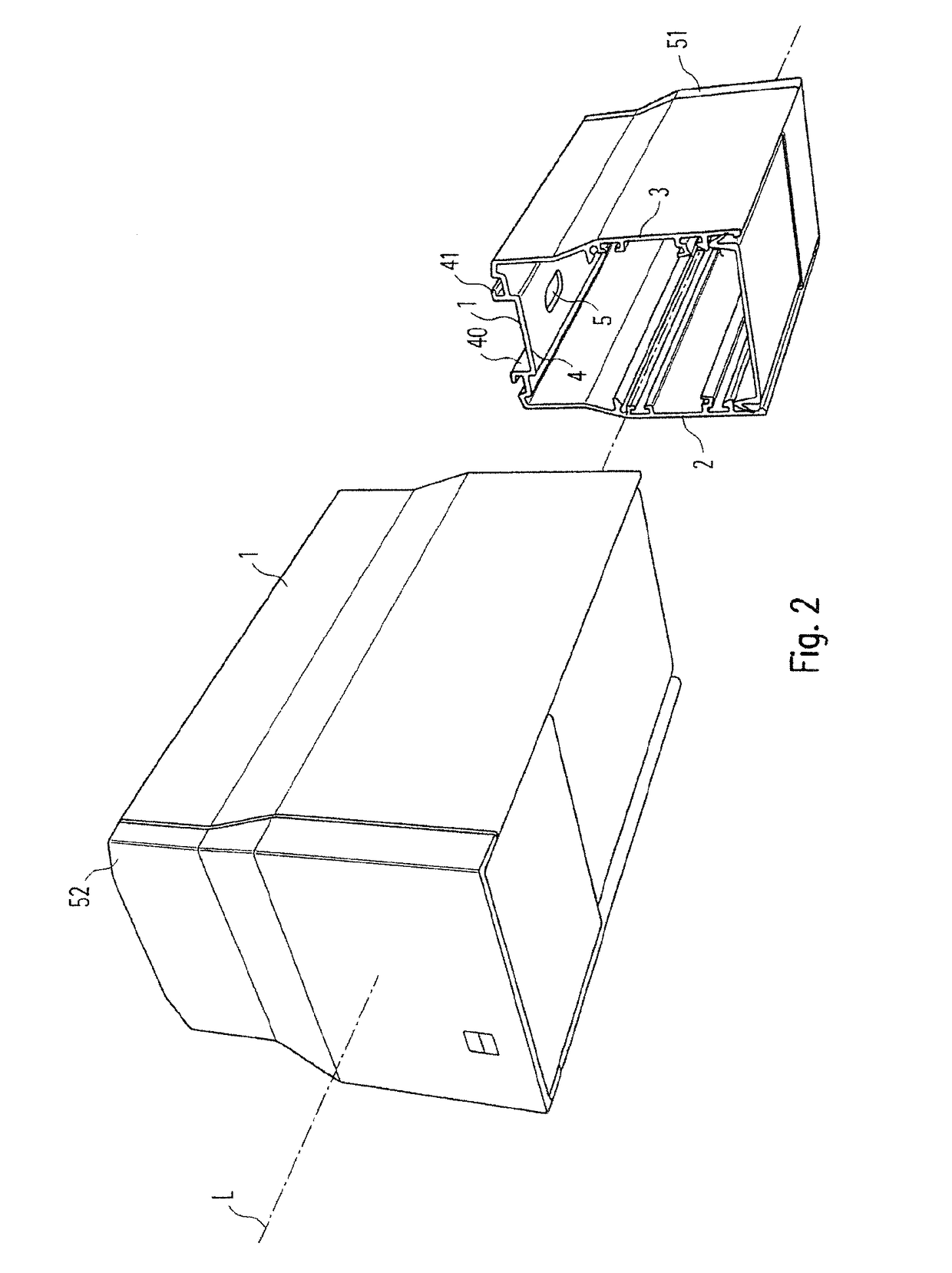
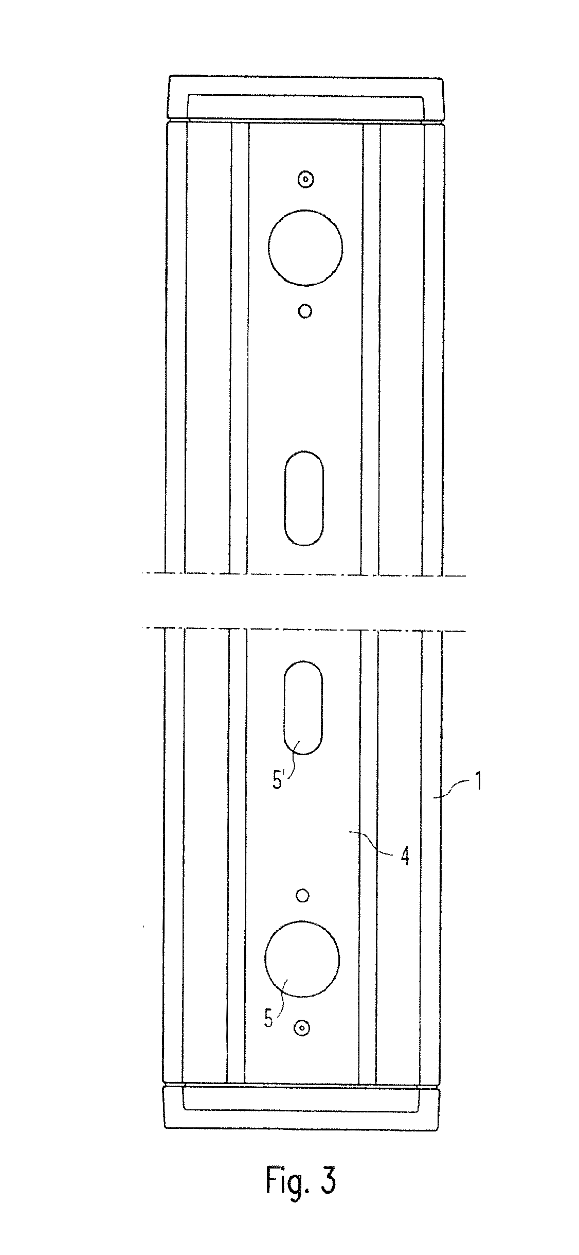
[0024]The invention relates to a strip light system with a carrier rail 1, as shown in perspective in sectional form in FIG. 2; FIG. 4 shows a representation, corresponding to that shown in FIG. 2, with partially transparent boundaries. The carrier rail 1 is elongated and extends along a longitudinal axis L. In particular, the carrier rail 1 may be designed as a profile element. Preferably the carrier rail 1 is made of a metal, for example, aluminum.
[0025]The carrier rail 1 has a U-shape in a cross section normal to the longitudinal axis L, when viewed in a first approximation, so that a first U leg 2, a second U leg 3 and a connecting leg 4, connecting the first U leg 2 to the second U leg 3, are formed. In particular, the carrier rail 1 is provided to be aligned in such a way in order to operate the strip light system that the first U leg 2 and the second U leg 3 point downwards, and the connecting leg 4 points upwards.
[0026]In particular, the connecting leg 4 may be designed so a...
PUM
 Abstract
Description
Claims
Application Information