Radio Communication Receiver Cancelling Out The Cross Polarisation Of A Received Signal

a radio communication receiver and cross polarisation technology, applied in the field of digital receivers, can solve the problems of interference degrading the bit error rate at reception, and affecting the operation of transmission techniques. the effect of variable envelope modulation

Active Publication Date: 2019-01-31
ZODIAC DATA SYSTEMS +1
View PDF4 Cites 2 Cited by
  • Summary
  • Abstract
  • Description
  • Claims
  • Application Information

AI Technical Summary

Problems solved by technology

One problem is that the isolation performances between polarisations of receiving and sending antennas as well as atmospheric propagation create interference between crossed polarisations.
In general, the signals coming from both approximately orthogonal of the antenna can be demodulated, but interference degrades the bit error rate at reception.
However, these techniques function less well with variable envelope modulations such as filtered modulations, the constellations presenting symbols of different energies or communications in bursts.
In particular, these models do not allow joint equalisation processing.
Known solutions such as that described in EP1940061A1 need carrier phase recovery prior to cancellation or demodulation, which is not possible with modulations received at very low signal-to-noise ratio, such as those using powerful codings (turbo codes or LDPC) to operate at the limit of the Shannon capacity, or in the presence of major interference from crossed polarisation.
Others such as EP2560306A1 or EP307950A2 propose improving processing of interference via a transverse filter by adding a temporal realignment system of the secondary polarisation on the main, which complicates the device.
These devices estimate error criteria from variations with former symbols where the signal-to-noise ratio or signal-to-interference ratio is low and therefore disallows equalisation on waveforms provided for functioning near the Shannon limit.
Therefore, known solutions are complex and need upstream processing and do not apply to all communication cases.

Method used


Image

  • Radio Communication Receiver Cancelling Out The Cross Polarisation Of A Received Signal
  • Radio Communication Receiver Cancelling Out The Cross Polarisation Of A Received Signal
  • Radio Communication Receiver Cancelling Out The Cross Polarisation Of A Received Signal

Examples


first embodiment

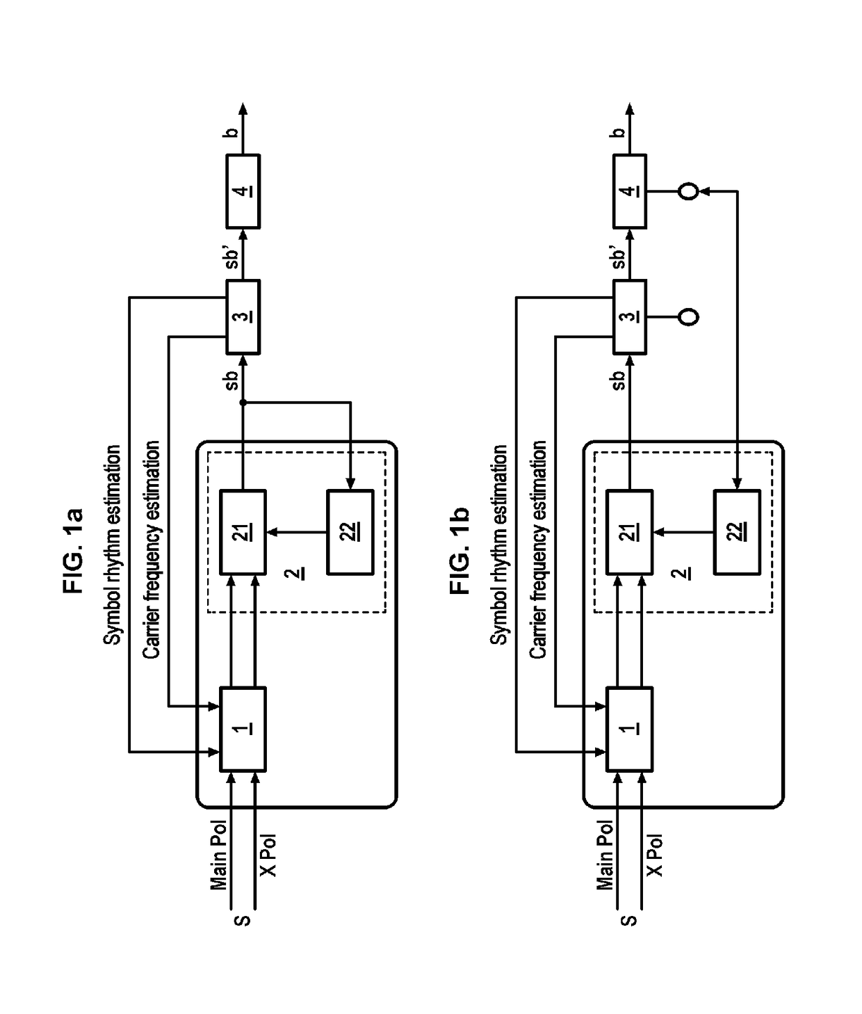
[0086]FIG. 1a illustrates a receiver where the cancellation unit 2 of the interference functions in blind mode without need for a demodulation unit 3. According to this first embodiment, the filters at any given time are estimated from the filtered signal at output of the filtering unit 2) the preceding instant.

[0087]FIG. 1b illustrates a receiver where the cancellation unit 2 of the interference takes at its input a signal coming from the demodulation unit 3 or a signal coming from the decoding unit 4.

[0088]According to a second embodiment, the cancellation unit 2 of the secondary polarisation takes at its input a signal coming from the demodulation unit 3 so as to calculate its error signal updating its filter by maximising the signal-to-noise ratio and / or its signal-to-distortion ratio channel. In this second embodiment, it is the symbols filtered by the adapted filter of the demodulation unit 3 which are used for estimating the filters of the estimation unit 22 of the filter.

third embodiment

[0089] the filters of the estimation unit 22 of the filter are estimated from the information symbols affected by probability (symbols sb′).

[0090]In FIG. 1b the interrupter returning the symbols is positioned on the decoding unit 4 or on the demodulation unit 3. When it is on the demodulation unit 3 this corresponds to the second or third embodiment depending on viewpoint after the adapted filter or after equalisation and supple demapping symbol.

[0091]With respect to the second and third embodiments, it is said that the receiver is in non-blind mode, or Data Aided or at a minimum the constellation of the signal is known so that it is synchronised correctly in the region of the receiving unit 1, and the filter is correctly estimated. In such a case, the received signal comprises expected symbols which can retrieve the rhythm or frequency information supplied to the receiving unit 1. These symbols could be used in the second embodiment. Therefore, for these embodiments relative to the...

fourth embodiment

[0092] the filters are estimated from the extrinsic information symbols b at output of the decoding unit 4.

[0093]With respect to the fourth embodiment, estimation of the filter is done by methods known as iterative consisting of minimising the error probability represented by the extrinsic information of the unit 4, the algorithm BCJR could for example be used, or backward-forward.

[0094]Also, the coefficients of filters are regularly corrected by a gradient method, Newton or other converging towards the optimal solution.

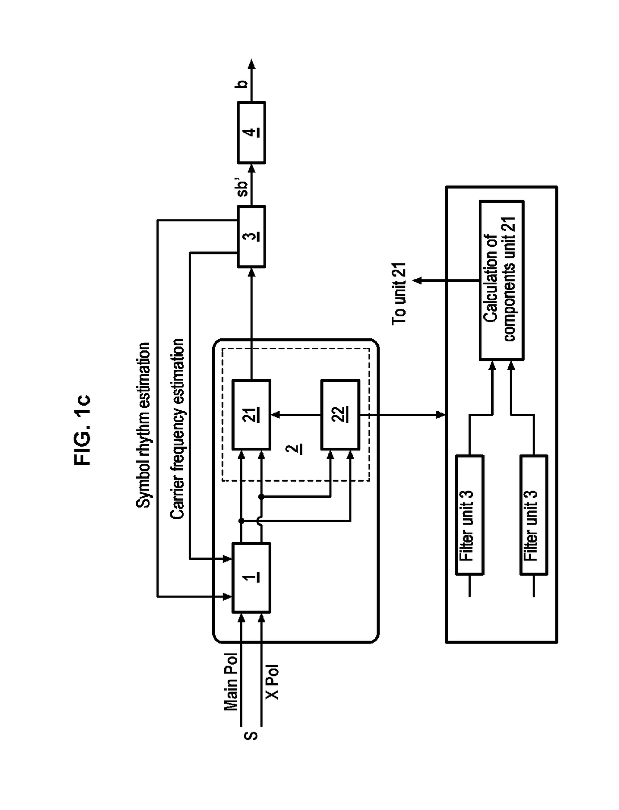
[0095]According to a fifth embodiment, illustrated in FIG. 1c, the receiver is similar but the filters of the cancellation unit 2 of the secondary polarisation are estimated from the signals synchronized by the unit 1 and filtered by the filters of interest of the unit 3 duplicated in the estimation unit 22 of the filter on each of the inputs, according to FIG. 1b. This fifth mode is mathematically equivalent to the second, third and fourth embodiments in that the fi...


PUM


Abstract

The invention relates to a radio communication receiver receiving a radio signal (S) including a main polarisation (MAIN-POL) and a secondary polarisation (X-POL) orthogonal to the main polarisation (MAIN-POL), the receiver including: a unit (1) for receiving the main polarisation (MAIN-POL) and the secondary polarisation of the received signal, synchronised as a carrier frequency with the main polarisation (MAIN-POL); a unit (2) for cancelling out the secondary polarisation synchronised with the main polarisation (MAIN-POL) and configured to suppress, from the received signal (S), the interference due to the secondary polarisation (X-POL), the unit (2) for cancelling out the secondary polarisation including a filtering unit (21) that receives the main polarisation (MAIN-POL) and the secondary polarisation (X-POL) as input; a unit (3) for demodulating the filtered signal, located downstream of the cancellation unit and configured to calculate carrier frequency error information and to communicate same by feedback to the upstream receiving unit (1).

Description

GENERAL TECHNICAL FIELD[0001]The invention relates to a digital receiver and especially a receiver configured to cancel interference due to crossed polarisation of a signal comprising two orthogonal polarisations.PRIOR ART[0002]In terms of radio communications, the bulk of the frequential spectrum is such that to optimise the spectral resource radio signals are transmitted in two orthogonal polarisations. This is particularly true for directive communications encountering few obstacles, such as communications by satellite or terrestrial transmitters. In this way, spectral capacity is doubled.[0003]One problem is that the isolation performances between polarisations of receiving and sending antennas as well as atmospheric propagation create interference between crossed polarisations.[0004]In general, the signals coming from both approximately orthogonal of the antenna can be demodulated, but interference degrades the bit error rate at reception.[0005]This effect is the greatest for c...

Claims


Application Information

Patent Timeline
Patent Type & Authority Applications(United States)
IPC IPC(8): H04B7/10H04B17/336H04B7/00H04B7/04
CPCH04B7/10H04B17/336H04B7/002H04B7/04
Inventor PASTERNAK, NICOLASTHOMAS, ALAINDUDAL, CLEMENTLLAURO, MATHIEUMILLERIOUX, JEAN-PIERRE
Owner ZODIAC DATA SYSTEMS
Why Eureka
Try Eureka