Transparent Proxy Architecture for Multi-Path Data Connections

Active Publication Date: 2013-05-02
ATTILA TECH
View PDF13 Cites 212 Cited by
  • Summary
  • Abstract
  • Description
  • Claims
  • Application Information

AI Technical Summary

Benefits of technology

[0008]Principles of the invention, in illustrative embodiments thereof, advantageously provide a system for forming an optimal communication connection to support the needs of advanced real-time mobile applications. Unique capabilities of the system include, but are not limited to, an ability to dynamically leverage and aggregate individual capabilities of all available networks simultaneously so as to form an ideal “communications pipe” (e.g., an enhanced data connection aggregating one or more capabilities of respective individual access networks forming the communications pipe), thus

Problems solved by technology

However, due at least in part to the lack of implicit acknowledgments, UDP cannot guarantee reliability, ordering or integrity of the data.
In a wired network, random bit error rate (BER), a characteristic usually more pronounced in a wireless network environment, is negligible, and congestion is a main cause of packet loss.
However, this assumption does not necessarily hold true when the end-to-end path also includes wireless links.
Factors including, for example, high BER, unstable channel characteristics, and user mobility, may all contribute to packet losses.
Many studies have shown that an unmodified standard TCP performs poorly in a wireless communications environment due, at least in part, to its inability to distinguish packet losses caused by network congestion from those losses attributed to transmission error

Method used


Image

  • Transparent Proxy Architecture for Multi-Path Data Connections
  • Transparent Proxy Architecture for Multi-Path Data Connections
  • Transparent Proxy Architecture for Multi-Path Data Connections

Examples


Example

[0032]It is to be appreciated that elements in the figures are illustrated for simplicity and clarity. Common but well-understood elements that may be useful or necessary in a commercially feasible embodiment may not be shown in order to facilitate a less hindered view of the illustrated embodiments.

DETAILED DESCRIPTION OF PREFERRED EMBODIMENTS

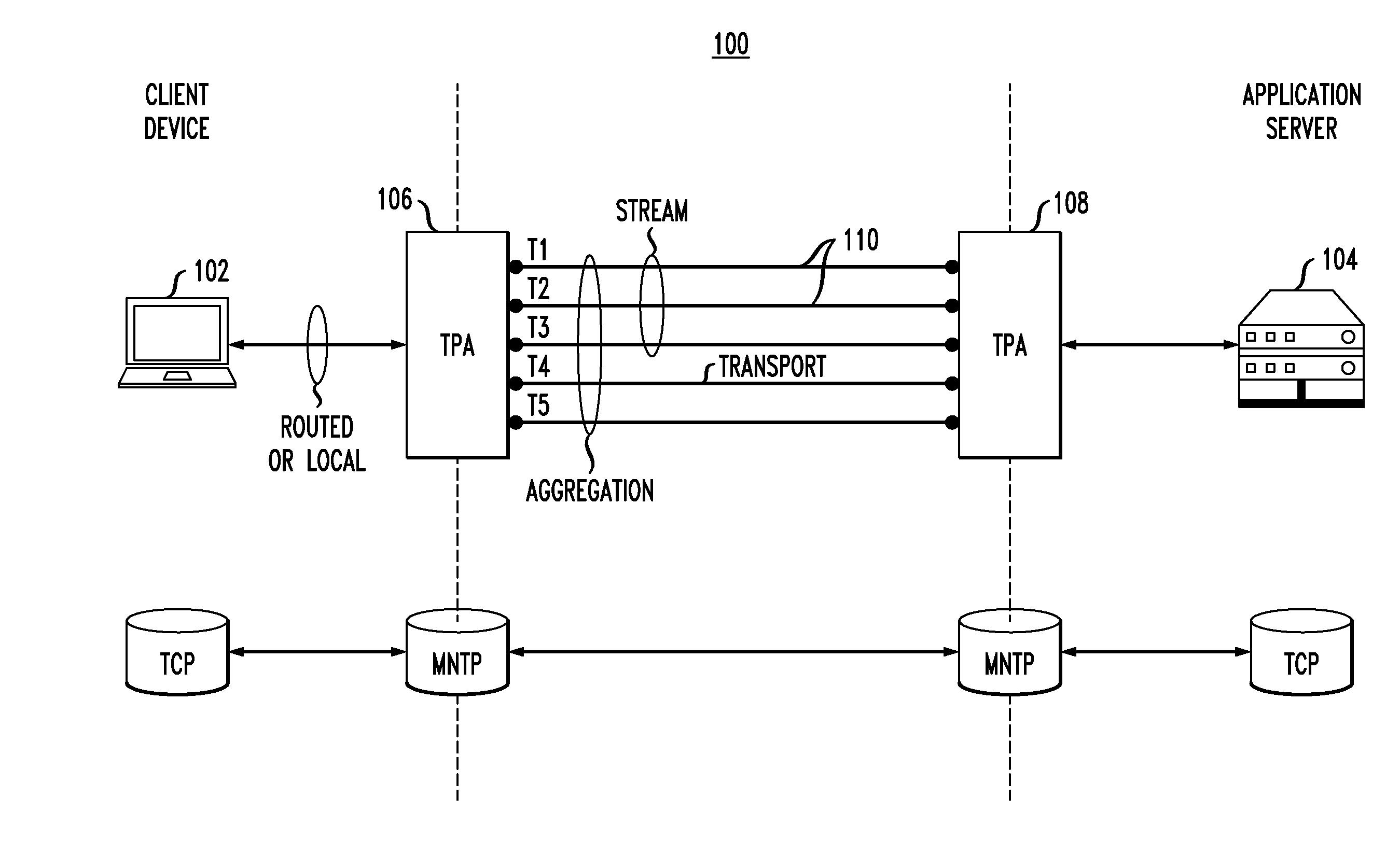
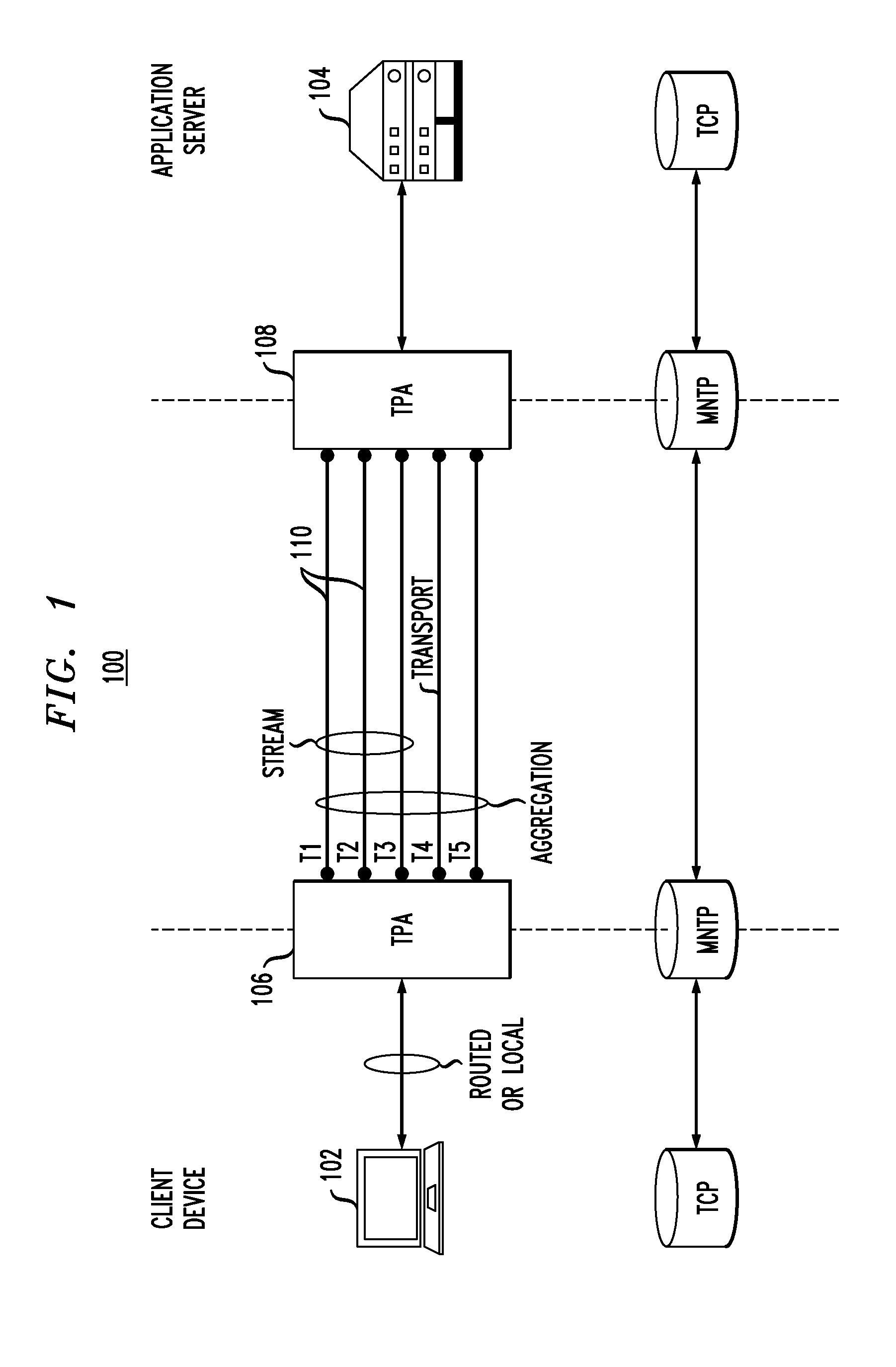
[0033]Principles of the present invention will be described herein in the context of illustrative embodiments of a transparent proxy architecture (TPA) for multi-link data connections that aim at optimizing the performance of any application(s) over multiple wired or wireless data connections. The TPA replaces the legacy TCP protocol or any optimized TCP implementations with a transport protocol capable of taking advantage of a plurality of possible data connections between the proxy endpoints, while being fully transparent to legacy applications. One or multiple network connections are available between each multi-homed TPA endpoint. Among ot...


PUM


Abstract

A method for forming an optimized communication connection providing enhanced performance of at least one application utilizing the communication connection is provided, the communication connection including a plurality of individual communication networks. The method includes the steps of: obtaining a set of performance requirements corresponding to the application utilizing the communication connection; obtaining real-time capacity information for each of a plurality of available channels associated with the respective individual communication networks; applying at least one policy-based management criteria to the available channels for controlling, in real-time, one or more aspects of the available channels; dynamically aggregating the individual communication networks to form the optimized communication connection, the communication connection leveraging one or more features and capabilities of at least a subset of the communication networks; and controlling real-time traffic scheduling across at least a subset of the available channels so as to adapt the communication connection to changes in network conditions and/or policy-based management criteria.

Description

CROSS-REFERENCE TO RELATED APPLICATION(S) [0001]This application claims the benefit of U.S. Provisional Application No. 61 / 362,764 filed on Jul. 9, 2010, the disclosure of which is incorporated herein by reference in its entirety.FIELD OF THE INVENTION [0002]The present invention relates generally to the electrical, electronic, and computer arts, and more particularly relates to electronic device communications.BACKGROUND OF THE INVENTION[0003]The Internet provides a platform for rapid and timely information exchange among a disparate array of clients and servers. Transmission control protocol (TCP) and Internet protocol (IP) are well-known separately designed and closely tied protocols that define rules of communication between end hosts, and are presently the most commonly used protocol suite for transferring data via the Internet. The combination of TCP / IP dominates modern communications over various networks, from a wired backbone to a heterogeneous network, due primarily to its...

Claims


Application Information

Patent Timeline
IPC IPC(8): H04L29/08H04L45/243H04L47/80H04L47/2475H04L47/762
CPCH04L43/0852H04L43/0888H04L45/245H04L47/2475H04L47/762H04L29/0818H04W48/16H04W72/12H04W76/02H04W80/06H04W88/182H04L47/785H04W76/10H04L67/01H04L67/56H04L67/101H04L69/08H04L69/16H04L43/0882H04L47/801H04L47/803
Inventor GIRARD, NICOLAS
Owner ATTILA TECH
Why Eureka
Try Eureka