Connector suitable for use in jewelry

Inactive Publication Date: 2019-02-07
BOGIN MICHA
View PDF3 Cites 0 Cited by
  • Summary
  • Abstract
  • Description
  • Claims
  • Application Information

AI Technical Summary

Benefits of technology

[0034]Such partial or complete covering of the seam (whether by the male or by the female body) helps reduce, if not entirely eliminates, separation of a connected male and female components by insertion of an object (accidental or not) into the seam to pry the two components apart.
[0035]In some embodiments, a connector according to the teachings herein is configured so that when the male component is connected to the female component, substantially no tilting motion of the retention pin relative to the perforation perpendicular to the axis is possible. by “configured” is meant that parts of the male component and the female component are shaped, dimensioned and/or include features so that when the male component is

Problems solved by technology

Many known connectors have disadvantages when used in jewelry, often including one or more of: not being sufficiently secure or being fine and consequently weak,

Method used


Image

  • Connector suitable for use in jewelry
  • Connector suitable for use in jewelry
  • Connector suitable for use in jewelry

Examples


Example

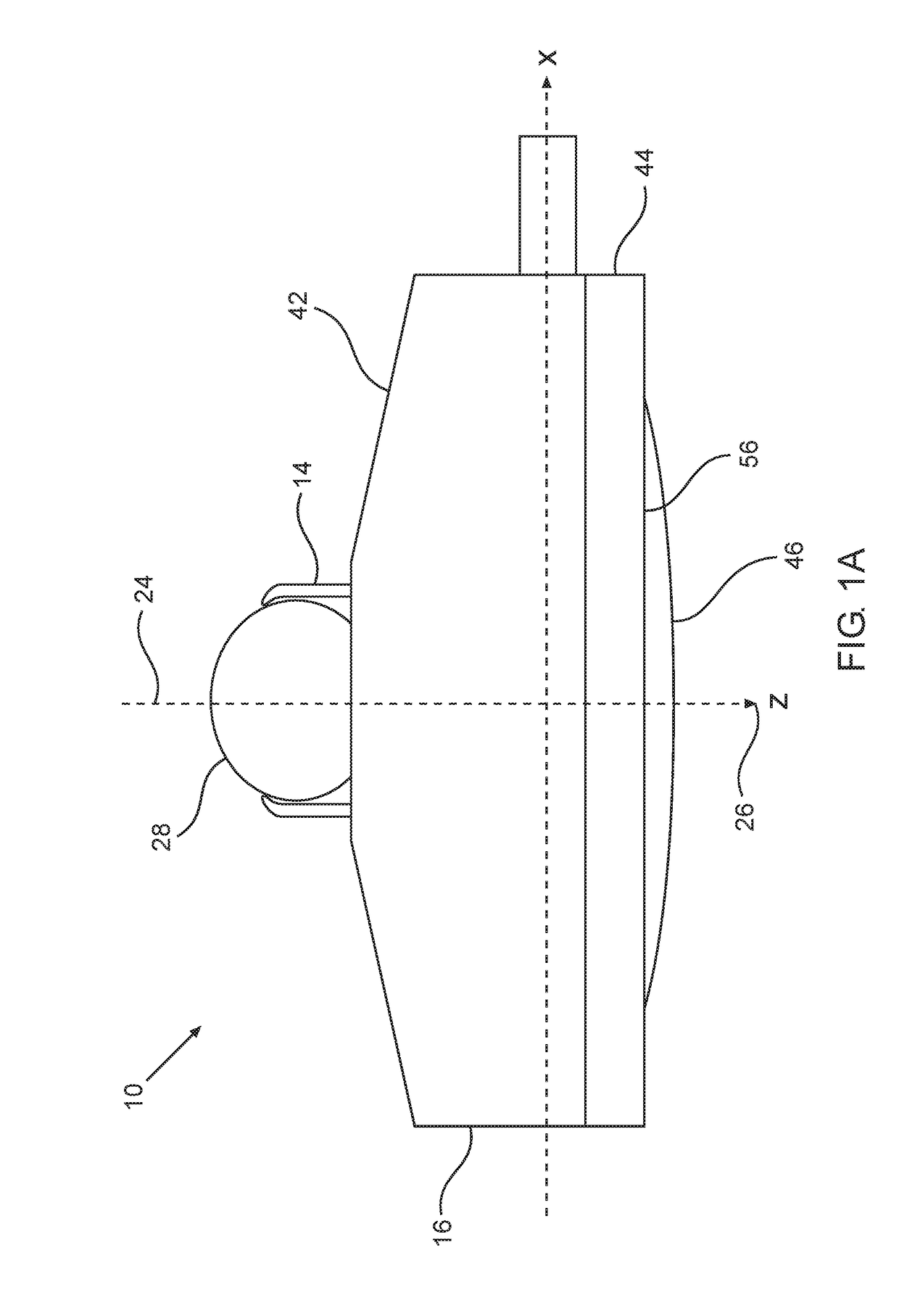
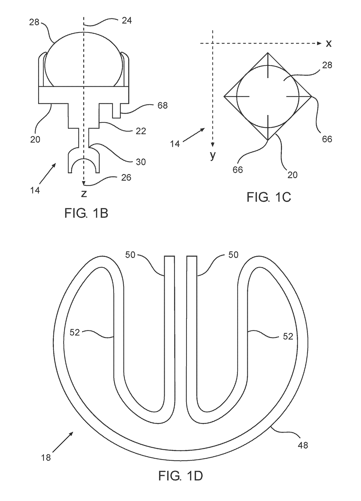
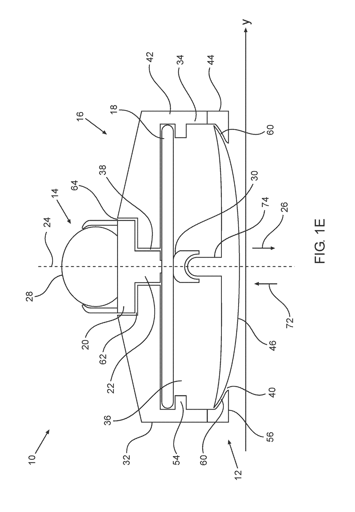
[0084]Some embodiments of the invention relate to connectors suitable for use with jewelry.

[0085]The principles, uses and implementations of the teachings of the invention may be better understood with reference to the accompanying description and figures. Upon perusal of the description and figures present herein, one skilled in the art is able to implement the teachings of the invention without undue effort or experimentation. In the Figures, like reference numerals refer to like parts.

[0086]Before explaining at least one embodiment in detail, it is to be understood that the invention is not necessarily limited in its application to the details of construction and the arrangement of the components and / or methods set forth herein. The invention is capable of other embodiments or of being practiced or carried out in various ways. The phraseology and terminology employed herein are for descriptive purpose and should not be regarded as limiting.

[0087]As discussed in the background abo...


PUM


Abstract

Disclosed is a connector suitable for use in jewelry, comprising a female component configured for reversible mating with a male component.

Description

RELATED APPLICATION[0001]The present application gains priority from UK Patent Application GB 1603687.3 filed 3 Mar. 2016, which is included by reference as if fully set-forth herein.FIELD AND BACKGROUND OF THE INVENTION[0002]The invention, in some embodiments, relates to the field of connectors, and more specifically, to connectors suitable for use in jewelry.[0003]The use of connectors in jewelry is well known for various purposes including:[0004]reversibly securing piercing jewelry such as earrings and studs to the body of a wearer; reversibly attaching ends of elongated encircling jewelry such as necklaces and bracelets when putting on or removing the jewelry from a wearer; and reversibly associating a decorative element from an item of jewelry, such as a gem stone of a ring or pendant.[0005]Many known connectors have disadvantages when used in jewelry, often including one or more of: not being sufficiently secure or being fine and consequently weak, therefore risking undesirabl...

Claims


Application Information

Patent Timeline
IPC IPC(8): A44B17/00
CPCA44B17/0011A44C15/0035A44C5/2076A44C7/003A44C5/20A44C15/005
Inventor BOGIN, MICHA
Owner BOGIN MICHA
Why Eureka
Try Eureka