Nuclear magnetic resonance (NMR) probe

Inactive Publication Date: 2008-10-23
HITACHI LTD
View PDF3 Cites 1 Cited by
  • Summary
  • Abstract
  • Description
  • Claims
  • Application Information

AI Technical Summary

Benefits of technology

[0010]According to the present invention, the length of the high-frequency cable between the probe coil and the preamplifier can be shortened remarkably and consequently the loss caused in the h

Problems solved by technology

As a result, the loss in the transmission cable tends to increas

Method used


Image

  • Nuclear magnetic resonance (NMR) probe
  • Nuclear magnetic resonance (NMR) probe
  • Nuclear magnetic resonance (NMR) probe

Examples


first embodiment

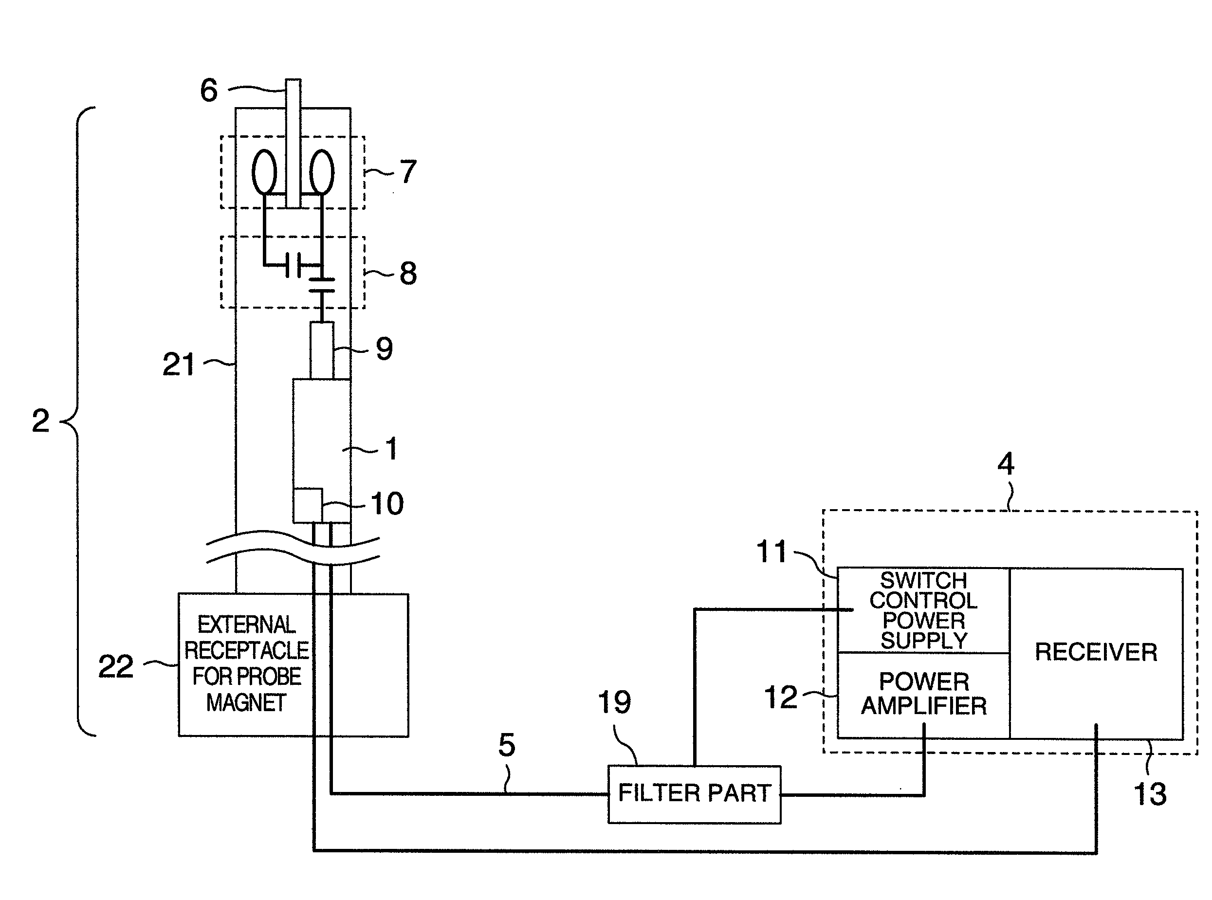
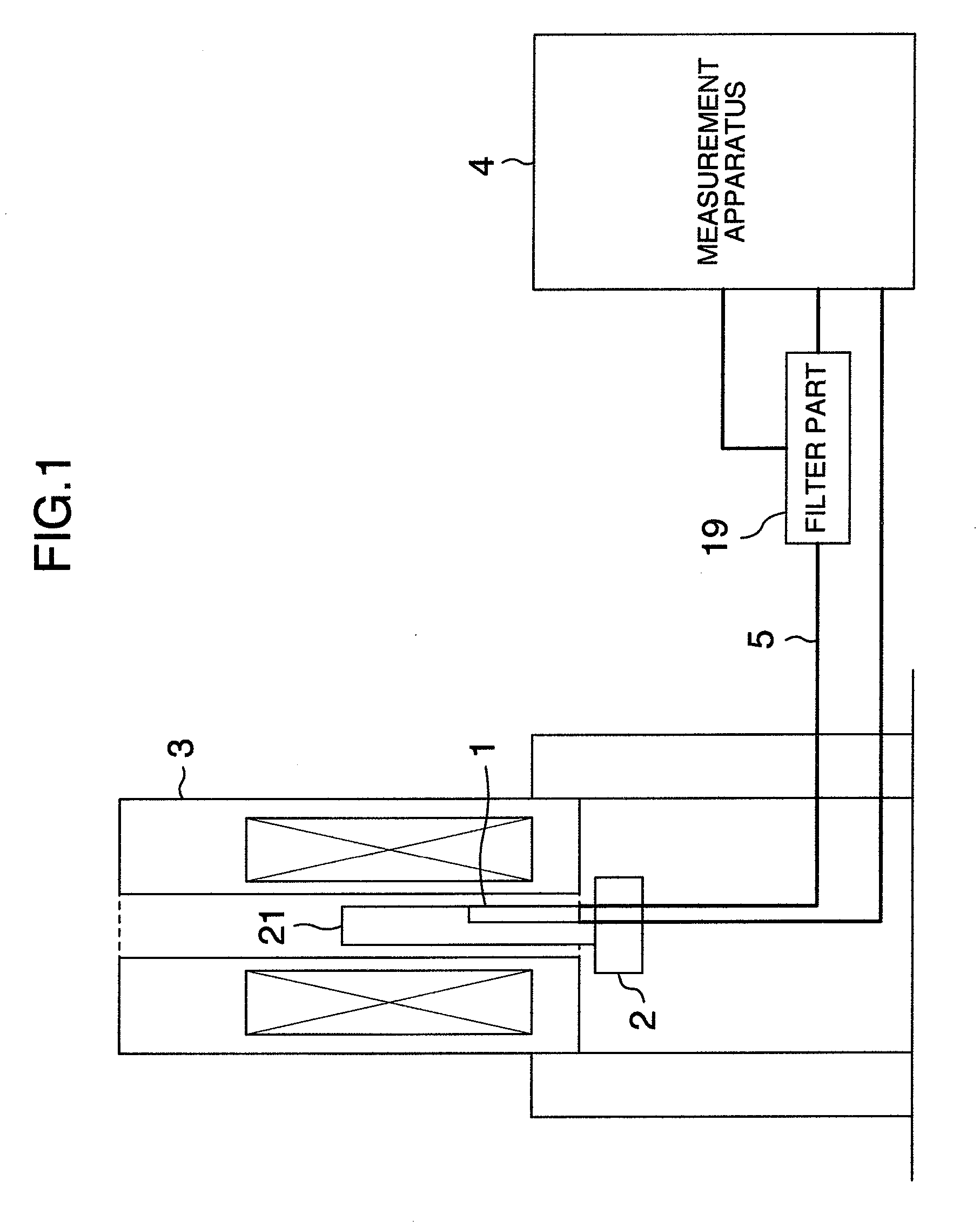
[0026]FIG. 1 is a schematic diagram of an NMR apparatus according to a first embodiment of the present invention. The changeover switch 1 is disposed in the probe body 21 which is a long and slender part of the probe, and is connected to an external measurement apparatus 4 via a transmission cable 5 in order to conduct signal processing. The changeover switch is accommodated in a region of an NMR magnet 3 in a cryostat by disposing the probe 2 in the magnet.

[0027]FIG. 2 is a configuration diagram showing details of the NMR probe and the measurement apparatus in the first embodiment. The details will now be described while comparing FIG. 2 with FIGS. 9A and 9B which are configuration diagrams of conventional NMR probes. In FIGS. 2, 9A and 9B, a probe coil 7 and a tuning circuit 8 are connected to the changeover switch 1 by a transmission line 9. Selection of connection to a power amplifier 12 and a preamplifier 10 is conducted by a control signal generated by a switch control power s...

second embodiment

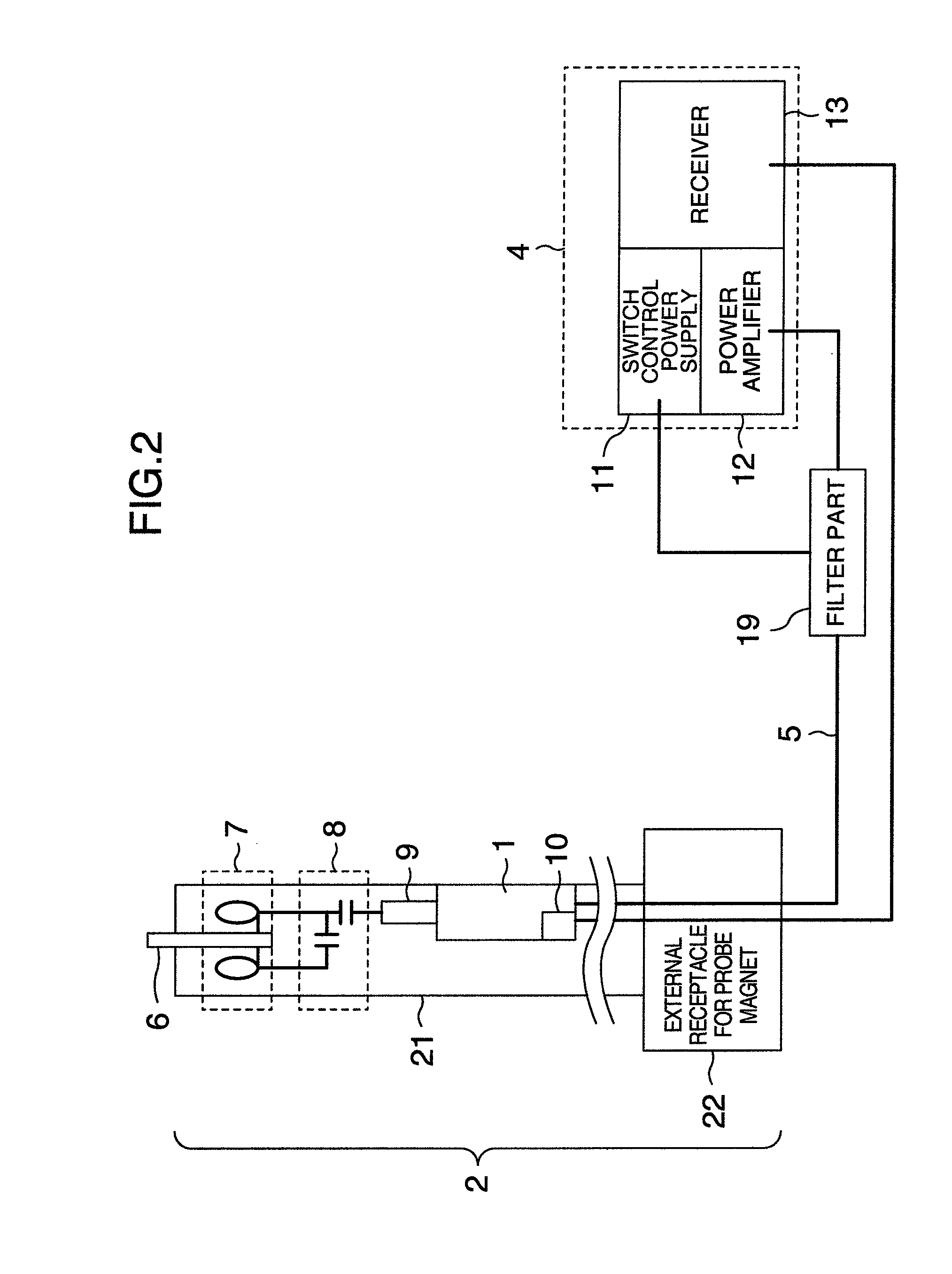
[0056]The changeover switch 1 according to the present invention is also effective to a low temperature probe in which the probe coil 7 is cooled. FIG. 6 shows a schematic configuration of a low temperature probe and an arrangement configuration of the changeover switch according to the present invention. In the low temperature probe, the probe coil 7 and the tuning circuit 8 are cooled by a heat exchanger 23. Noise contained in the original signal is much smaller as compared with the case of the probe at the room temperature, and the influence of the loss generated by the cable 9 as far as the preamplifier 10 becomes greater. A coolant cooled by a cooling apparatus 25 flows through a coolant transport pipe 26 and a coolant pipe 24 in the probe to cool the heat exchanger 23.

[0057]A second embodiment differs from the first embodiment only in the cooling configuration, and the mounting configuration and the operation of the changeover switch 1 are the same. The cooling configuration i...


PUM


Abstract

There is provided a nuclear magnetic resonance probe in which the loss caused by a high frequency cable between a probe coil and a preamplifier is reduced and the sensitivity of an NMR signal is improved. A changeover switch for NMR probe is divided into a switch part including switch elements and a filter part for filtering a switch control signal and an RF transmission signal. The switch part is disposed in a probe body inserted in a magnet of the probe. The filter part is disposed near a measurement apparatus located outside the probe. As for the switch part, a section structure of thickness and width is reduced in conformity with a narrow and slender shape of the probe body. The length of a high frequency cable between the probe coil and the preamplifier is shortened remarkably, and consequently the loss can be reduced.

Description

BACKGROUND OF THE INVENTION[0001]The present invention relates to a probe of a nuclear magnetic resonance apparatus, and in particular to a structure of a changeover switch.[0002]In the nuclear magnetic resonance (NMR) apparatus, detected signals are feeble. In application such as the structure analysis of protein, it is demanded to have a higher sensitivity. The NMR apparatus has a higher resolution and a higher sensitivity as the static magnetic field strength becomes strong. A superconducting magnet for generating the static magnetic field tends to become large in size (“Present Status of 920 MHz High-Resolution NMR Spectrometers,” Kiyoshi et al, IEEE Trans. Appl. Supercond. Vol. 14, pp. 1608-1612 (2004)). As a result, a probe for disposing a detection coil called probe coil in a magnetic field center of the static magnetic field is also being made longer.[0003]Since an NMR signal detected by the probe coil is very feeble, the NMR signal is typically amplified by a low noise pre-...

Claims


Application Information

Patent Timeline
IPC IPC(8): G01R33/34
CPCG01R33/34061G01R33/34092G01R33/3621G01R33/3664
Inventor FUKUDA, YUZOHAGIWARA, SHUYAKAWASAKI, KENJI
Owner HITACHI LTD
Why Eureka
Try Eureka