
Centrifugal casting apparatus and centrifugal casting method

Active Publication Date: 2019-05-23
HYUNDAI MOTOR CO LTD +1
View PDF0 Cites 0 Cited by
  • Summary
  • Abstract
  • Description
  • Claims
  • Application Information

AI Technical Summary

Benefits of technology

The present invention provides a centrifugal casting apparatus and method that can improve quality of products by reducing shrinkage defects and simplifying manufacturing process. By eliminating risers, which are often present in casted products, and increasing pressure effect, the overall process may be simplified, cost may be reduced, and the quality of products may be enhanced. Additionally, the method may reduce shrinkage defects, suppress bubble occurrence, and increase strength of the product through work hardening of the semi-solid or high-temperature solid shape.

Problems solved by technology

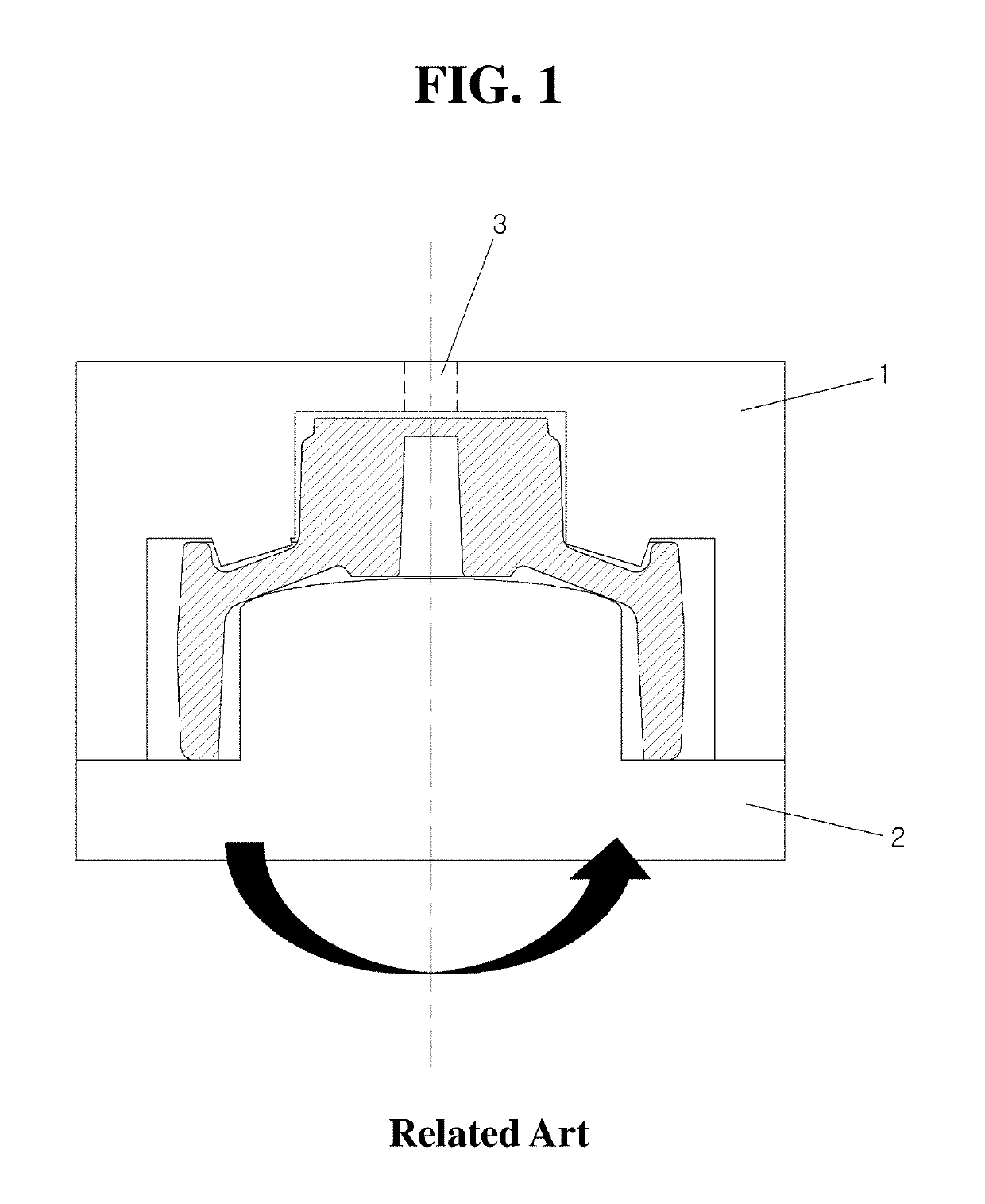
In the centrifugal casting process in which molten metal is injected during simultaneous rotation of the upper and lower molds and molding is performed by a centrifugal force of the molten metal, scraps occur due to excessive risers since the molds are rotated due to the nature of the process, and thus, a separate pressurizing apparatus is unable to be mounted, shrinkage defects are generated in the product part due to cooling rate, and a further process for removing risers is required.
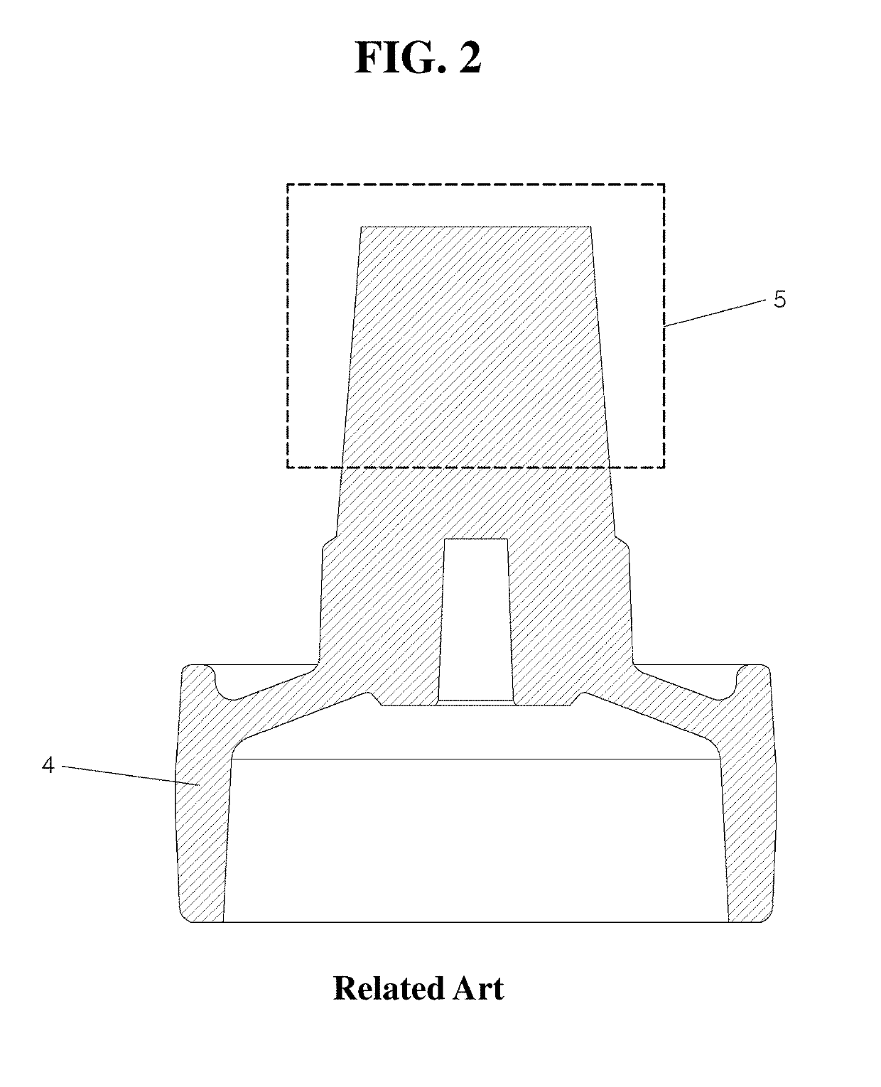
If the riser is not large, final solidification progresses in the product part rather than in the riser, which generates shrinkage defects in the product part.
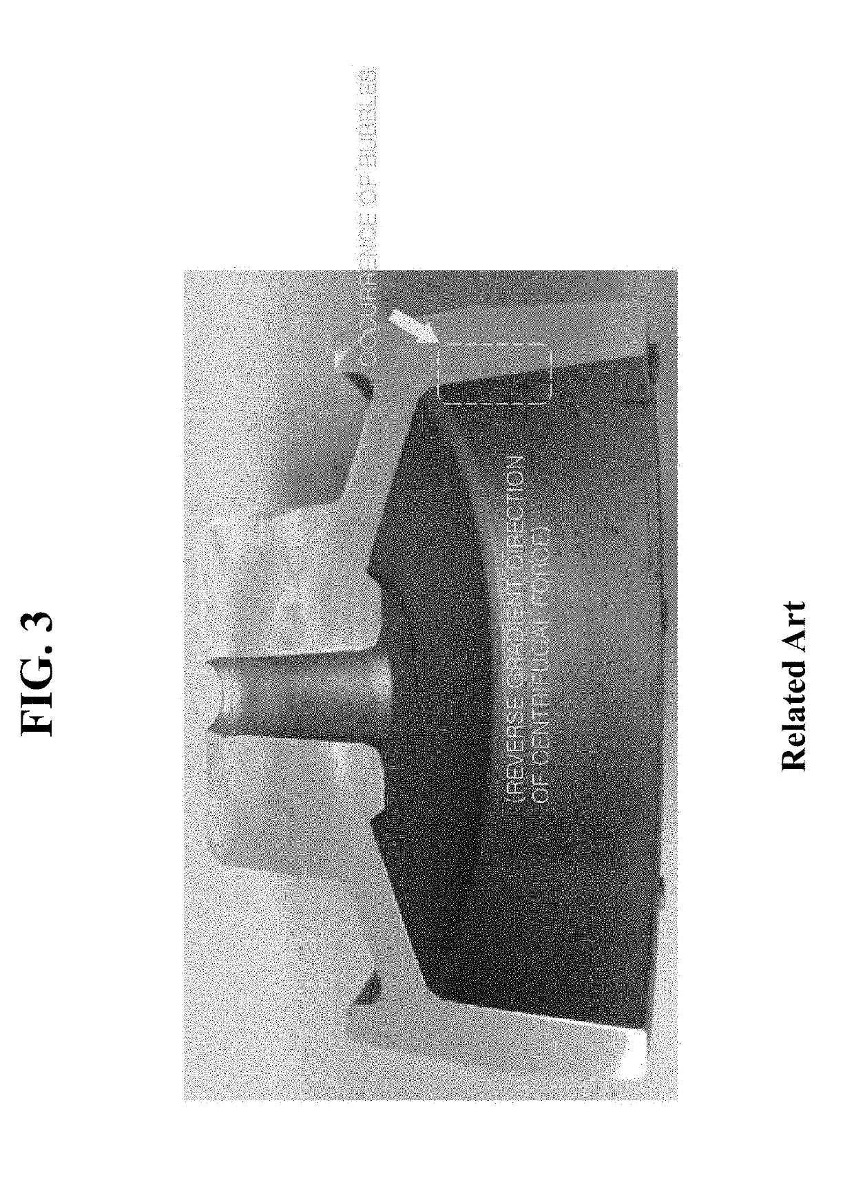
However, bubbles are still generated in the direction of the centripetal force as shown in FIG. 3 of the related art due to limitation of pressurizing force by the riser.

Method used


Image

  • Centrifugal casting apparatus and centrifugal casting method
  • Centrifugal casting apparatus and centrifugal casting method
  • Centrifugal casting apparatus and centrifugal casting method

Examples


Embodiment Construction

[0027]In order to fully understand the present invention, operational advantages of the present invention and objects achieved by implementing the present invention, the accompanying drawings exemplifying embodiments of the present invention and contents described in the accompanying drawings need to be referred to. In describing the exemplary embodiments, detailed description of technology known in the art or iterative description may be shortened or omitted to avoid obscuring the subject matter of the present invention.

[0028]The terminology used herein is for the purpose of describing particular embodiments only and is not intended to be limiting of the invention. As used herein, the singular forms “a”, “an” and “the” are intended to include the plural forms as well, unless the context clearly indicates otherwise. It will be further understood that the terms “comprises” and / or “comprising,” when used in this specification, specify the presence of stated features, integers, steps, ...


PUM

PropertyMeasurementUnit
Angleaaaaaaaaaa
Poweraaaaaaaaaa
Speedaaaaaaaaaa

Abstract

A centrifugal casting apparatus is provided. The centrifugal casting apparatus includes an upper mold machined to have an inner contour used to form an upper side surface of a casting, and a lower mold machined to have an inner contour used to form a lower side surface of the casting. An upper motor provides power to rotate the upper mold and a lower motor provides power to rotate the lower mold. The upper motor and the lower motor are operated independently of each other.

Description

CROSS-REFERENCE TO RELATED APPLICATIONS[0001]This application claims priority to Korean Patent Application No. 10-2017-0157444, filed on Nov. 23, 2017, the disclosure of which is incorporated herein by reference in its entirety.BACKGROUNDField of the Invention[0002]The present invention relates to a centrifugal casting apparatus and method for casting products using centrifugal force.Description of the Related Art[0003]A centrifugal casting method is used to manufacture high quality castings of complex shapes in the field of gravity casting, which is used to manufacture various automotive parts. FIG. 1 shows a centrifugal casting apparatus in the related art for casting a damper pulley that is one of automobile parts. In the conventional centrifugal casting method, a casting is manufactured in the form as shaped in a casting mold by joining together an upper mold 1 and a lower mold 2, which have an inner or an outer surface shape that corresponds to the outer shape of a casting, inj...

Claims


Application Information

Patent Timeline
IPC IPC(8): B22D13/04B22D13/10
CPCB22D13/04B22D13/101B22D13/12
Inventor KANG, MUN-GUKIM, YOUNG-CHANKIM, MIN-SOOKANG, HEE-SAM
Owner HYUNDAI MOTOR CO LTD
Learn More