Curtain airbag device mounting structure and curtain airbag deployment method

Active Publication Date: 2019-02-07
TOYOTA JIDOSHA KK
View PDF6 Cites 16 Cited by
  • Summary
  • Abstract
  • Description
  • Claims
  • Application Information

AI Technical Summary

Benefits of technology

[0033]According to the above configuration, upon activation of the inflator, the rear-side garnish is held in a state in which the rear-side garnish is apart way from the A-pillar via initial inflation of the curtain airbag. Then, the curtain airbag inflates and deploys from the gap between the rear-side garnish and the A-pillar while pressing the first side wall portion and the second side wall portion of the rear-side garnish apart from each other. Then, the curtain airbag is inflated and deployed toward the inner side of the vehicle cabin from between the first side wall portion and the second side wall portion pressed apart from each o

Problems solved by technology

Therefore, a position at which a curtain airbag is stored is limited and may possibly affect inflation and deployment of the curtain airbag.
Furthermore, as an example, if the curtain airbag is stored along the first pillar, when the curtain airbag inflates an

Method used


Image

  • Curtain airbag device mounting structure and curtain airbag deployment method
  • Curtain airbag device mounting structure and curtain airbag deployment method
  • Curtain airbag device mounting structure and curtain airbag deployment method

Examples


Example

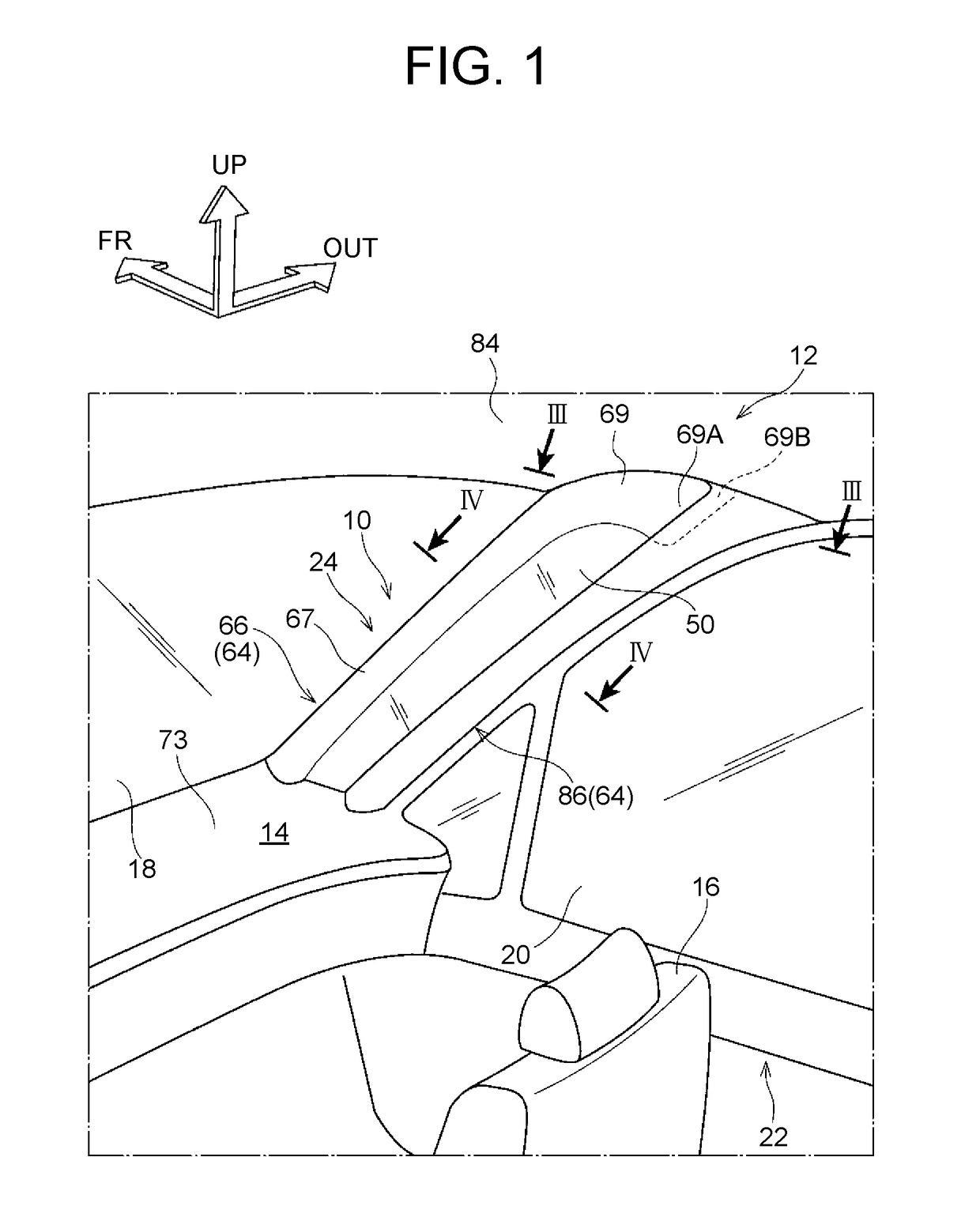
[0042]An embodiment of a curtain airbag device mounting structure according to the present disclosure will be described below with reference to FIGS. 1 to 7. Arrow FR indicated in each drawing denotes the front side in a front-rear direction of a vehicle, arrow OUT denotes the outer side in a width direction of the vehicle, and arrow UP denotes the upper side in a vehicle height direction.

[0043]As illustrated in FIG. 1, on the front side of a cabin 14 of a vehicle 12 to which a curtain airbag device mounting structure 10 according to the present embodiment is applied, a left-right pair of vehicle seats 16 are arranged, and a not-illustrated driver can sit on one of the vehicle seats 16. Here, as an example, the vehicle 12 in the present embodiment is a left-hand drive vehicle, and in the figure, illustration of the vehicle seat 16 on the driver's seat side is omitted.

[0044]On the vehicle front side relative to the vehicle seat 16, a front windshield (hereinafter simply referred to a...


PUM

PropertyMeasurementUnit
Thicknessaaaaaaaaaa
Shapeaaaaaaaaaa
Heightaaaaaaaaaa

Abstract

A curtain airbag device mounting structure includes: a first pillar forming a part of a front pillar and extends substantially along a vehicle height direction; a second pillar forming another part of the front pillar, the second pillar being disposed on a rear side of a vehicle relative to the first pillar at a predetermined distance from the first pillar and extending substantially along the vehicle height direction; a transparent member bridged between the first pillar and the second pillar; and a curtain airbag device including a curtain airbag stored along a roof side rail and the second pillar, the curtain airbag being configured to inflate and deploy in a curtain-like fashion over a side portion of a cabin of the vehicle in case of a collision of the vehicle.

Description

INCORPORATION BY REFERENCE[0001]The disclosure of Japanese Patent Application No. 2017-152636 filed on Aug. 7, 2017 including the specification, drawings and abstract is incorporated herein by reference in its entirety.BACKGROUND1. Technical Field[0002]The present disclosure relates to a curtain airbag device mounting structure and a curtain airbag deployment method.2. Description of Related Art[0003]Japanese Patent Application Publication No. 2006-273057 discloses a vehicle pillar structure. The vehicle pillar structure includes a front pillar (hereinafter referred to as “A-pillar”) inner panel, an A-pillar frame provided so as to face the front pillar inner panel, and an A-pillar garnish provided on the vehicle cabin side (vehicle interior side) of the A-pillar inner panel, and a transparent member is held by the A-pillar inner panel and the A-pillar frame. An opening is formed so as to extend through the A-pillar inner panel, the A-pillar frame and the A-pillar garnish in a thick...

Claims


Application Information

Patent Timeline
IPC IPC(8): B60R21/232B60R21/213B60R21/2338
CPCB60R21/232B60R21/213B60R21/2338B60R2021/23382B60R13/025B60R21/2334B62D25/04H01L2224/48477B01J2220/84H01L2224/78266A61B5/02021A46B11/0082A47F5/04A47F5/05A47F5/106A47F11/02A61M5/141A61B5/150022A61B5/150419A61B5/15045A61B5/151A61B5/15134B01J19/0093B22D11/06B22D11/0608B22D11/0657B22D11/0688B21D37/10B01J29/049B21D47/01B23D7/04B25D17/30B23K20/005B63B3/52B62D25/147B62D25/2036B60H1/243B62D27/065B60H1/265B60R21/21B62J1/08B65G41/008B62K19/36B66F7/02B65D51/1611D06F57/02E02F9/08E05B83/38E04B2/24E04B2/38E04B2/52E04B2/56E04B2/72E05C7/04E04G13/02E04C1/00E04C3/30F16C33/745F16M11/28F16K99/0017G02B6/4438G02B7/12G02F1/13394G02B23/18G05D23/126G09F15/00G09F15/0075G09F15/0081H01H35/30H01L21/76885H01L21/76208H01L29/7396H05K7/20336B01J2219/00367B29C65/548B60R2011/0022B60R2021/0435B65D2501/24235E04B2002/567H01L2221/1026H01L2224/78252H01L2224/78301H01L2224/78306H01L2224/78307H01L2224/78349H01L2224/83102H01L2225/1058H05K2203/0415B62J2001/085B01J2220/86H01L2224/40477H01L2224/77153H01L2224/77318H01L2224/77319H01L2224/77821H01L2224/78263H01L2224/78282H01L2224/78352H01L2224/78502H01L2224/78702H01L2224/78705H01L2224/78725H01L2224/78735H01L2224/78745H01L2224/78756H01L2224/78821H01L2224/85169H10N70/826B60R21/264B60R16/0207B60R21/013B60R13/02B60J5/0479B60J2005/0475B60J10/7775B60J7/0076
Inventor KOMURA, TAKAMICHIFUKAWATASE, OSAMU
Owner TOYOTA JIDOSHA KK
Why Eureka
Try Eureka