
Bipolar resectoscope

a resectoscope and bipolar technology, applied in the field of bipolar resectoscopes, can solve the problems of unfavorable varying current density, low density, and distance between the cutting loop of the active cutting electrode, and achieve the effect of convenient and cost-effectiveness

Active Publication Date: 2019-02-21
BOWA ELECTRONICS
View PDF0 Cites 2 Cited by
  • Summary
  • Abstract
  • Description
  • Claims
  • Application Information

AI Technical Summary

Benefits of technology

The patent is about a device used for resecting tissue in the male ureter. The device has a cutting loop with two electrically conductive contact tubes that are insulated from a fork. The exposed part of the device's neutral electrode is the roof section of the insulating insert, which makes it a continuous electrically conductive roof. This improves electrical safety and reduces the dependency of current density on the position of the shaft during resection. The shaft is made of an electrically conductive metal or material, which makes it easier to use in combination with an exterior shaft. Overall, the device ensures safe and efficient resection of tissue in the male ureter.

Problems solved by technology

The disadvantage here is that the electrode surface is of circumferential configuration, and inside the inlet area of the insulating insert high current density surges can occur on the cutting loop of the active cutting electrode, while the current density is rather too low and has a difficult ignition point for plasma generation when the cutting loop is extended and immersed into the tissue to be sectioned.
The disadvantage here is that, on the one hand, the distance between the active cutting electrode's cutting loop in the inlet area and the electrode surface of the neutral electrode is highly variable and requires higher currents, and, on the other hand, that the current density also greatly depends on the positioning of the shaft inside the patient's urethra.
The disadvantage here is that the electrically conductive tubular piece from the distal end of the insulating insert is arranged outside the inlet area to avoid direct contact of the cutting loop of the cutting electrode.
This, in connection with the surrounding tissue, depending on the positioning of the shaft in the male urethra, also leads to unwanted varying current densities.
The disadvantage here is that the surface of the neutral electrode must be relatively large and is extended with the cutting loop, thereby obstructing the field of vision of the optical unit.
Depending on the positioning of the resectoscope in the urethra, the extended electrode surface of the neutral electrode can come in contact with surrounding tissue and impact the current flow in an undesirable manner.

Method used


Image

  • Bipolar resectoscope
  • Bipolar resectoscope
  • Bipolar resectoscope

Examples


Embodiment Construction

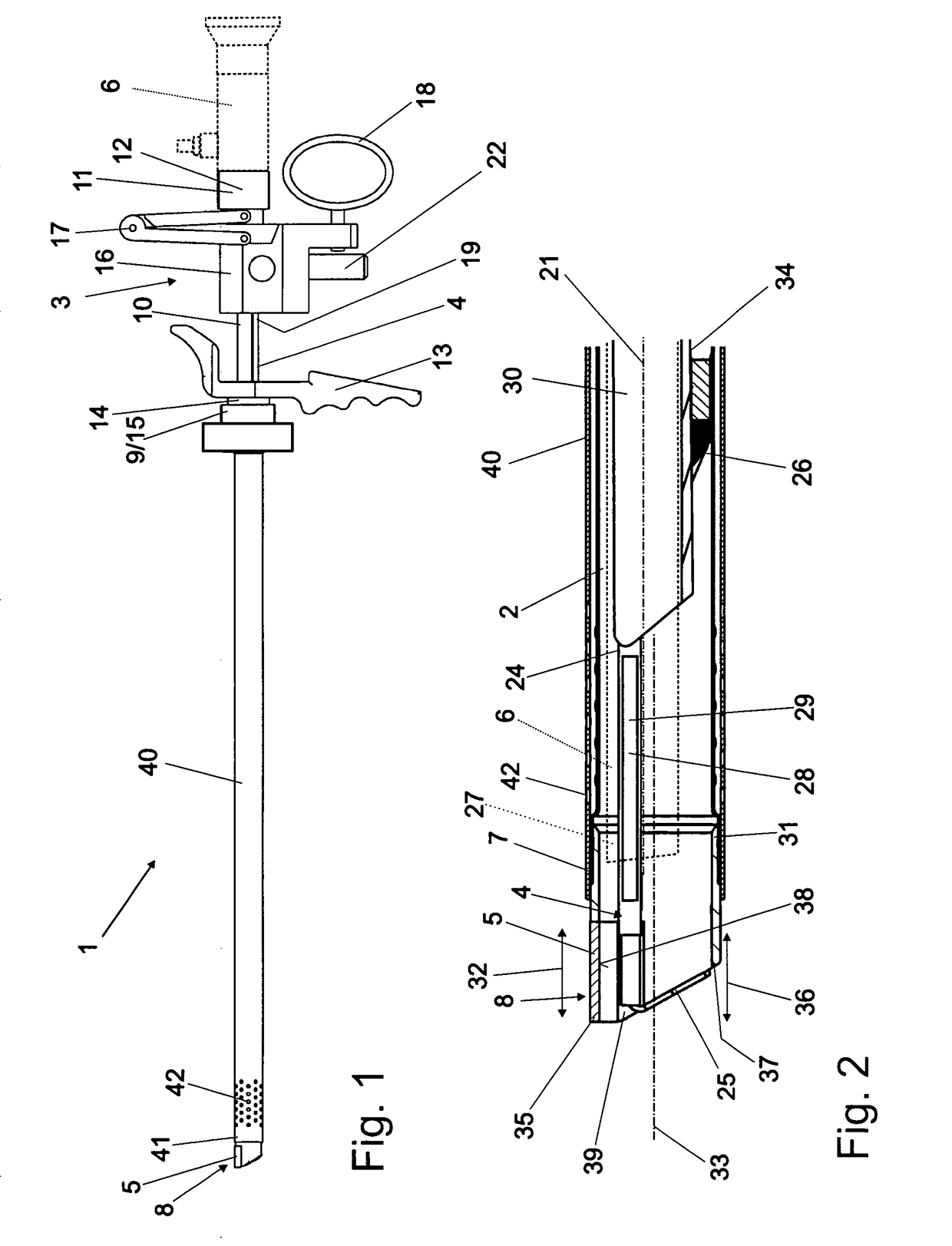
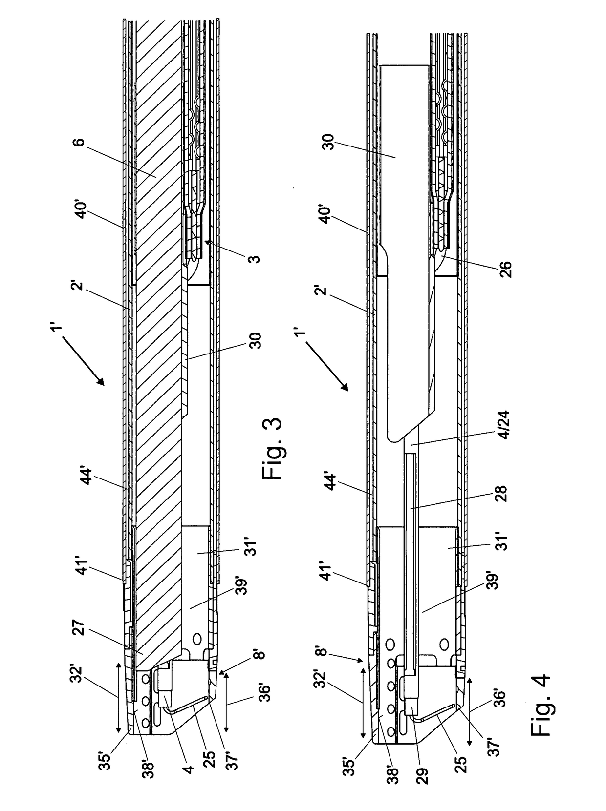
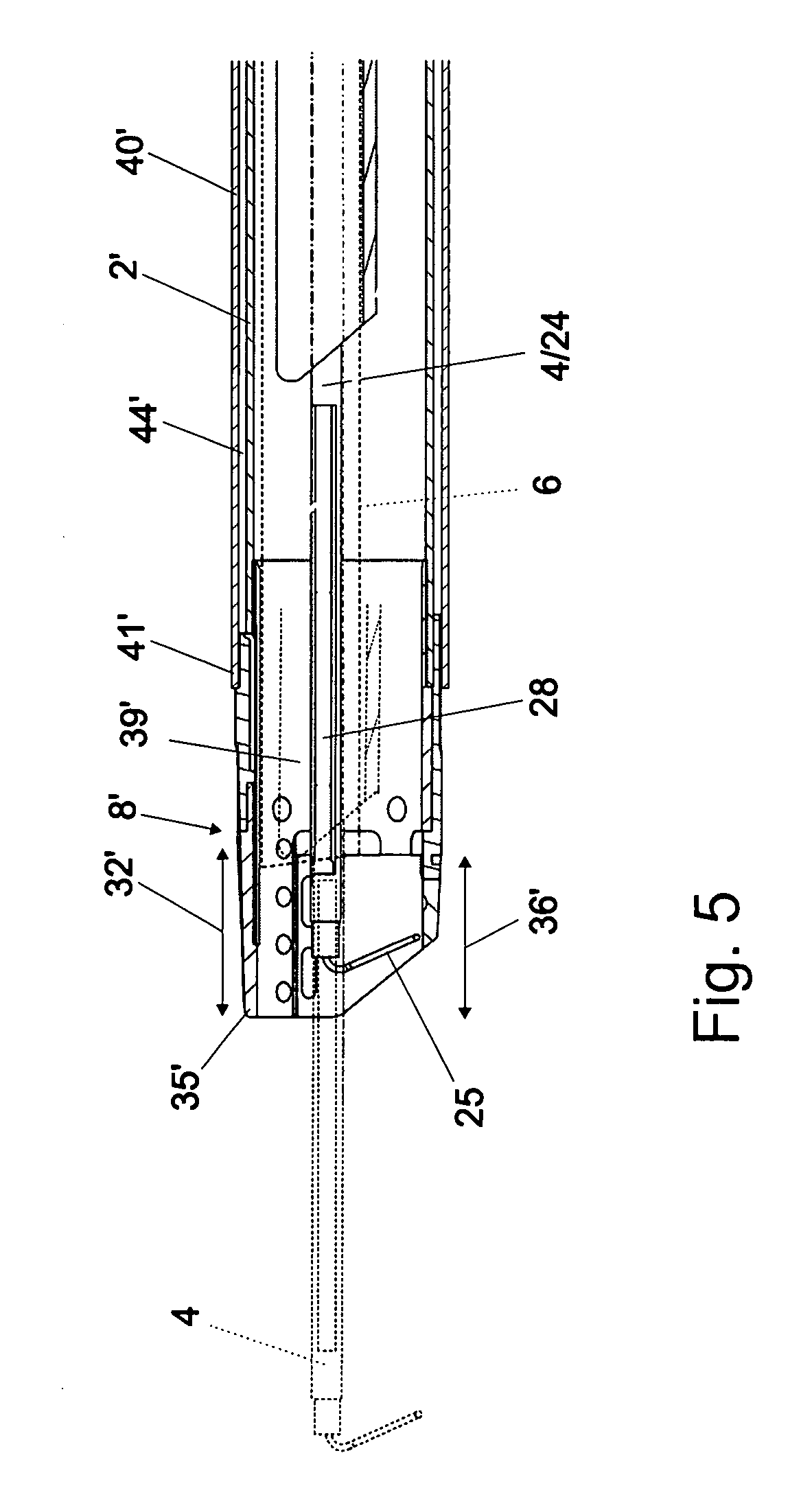
[0036]A bipolar resectoscope 1 essentially comprises a shaft 2, a working element 3, an active cutting electrode 4, a passive neutral electrode, and an optical unit 6.

[0037]At its distal end 7 facing the patient, the shaft 2 has an insulating insert 8. The working element 3 with the cutting electrode 4 can be inserted into the shaft 2 from its proximal end 9 facing away from the distal end 7 and be interlocked with the shaft 2.

[0038]The working element 3 has a guide tube 10 on whose proximal end 11 facing the operator a connector 12 is attached to connect an optical unit 6 which is guided inside the optical guide tube 10. The working element 3 comprises a finger grip 13 and an upstream connecting cone 14 in distal direction, in which the working element 3 can be interlocked with a main unit 15 forming the proximal end of the shaft 2.

[0039]A longitudinally displaceable sliding body 16 is mounted on the optical guide tube 10. The sliding body 16 is connected to the connector 12 via a ...


PUM


Abstract

A bipolar resectoscope (1) has a shaft (2, 2′) with an insulating insert (8) at its distal end (7). A working element (3) is mountable in the shaft (2, 2′) and a cutting electrode (4) is longitudinally displaceable in the shaft (2, 2′). The insulating insert (8) has an exposed conductive area of a neutral electrode (5, 5′). The area of the passive neutral electrode (5, 5′) exposed transverse to the longitudinal axis (34) forms an electrically conductive roof of the insulating insert (8, 8′). An inlet area (26) of the insulating insert (8, 8′) has an inner wall (38, 38′) with two opposing electrically conductive contact surfaces (39, 39′) of the neutral electrode (5, 5′) that are parallel to the longitudinal axis (33) and contact two parallel electrically conductive contact tubes (24) of a fork (26) and opening a cutting loop (25) of the cutting electrode (4).

Description

BACKGROUNDField of the Invention[0001]The invention relates to a bipolar resectoscope, comprising a shaft having an insulating insert made of an electrically non-conductive material at its distal end, where the insulating insert has at its exposed distal end facing away from the shaft an inlet area arranged vertically below the shaft's longitudinal axis for a cutting electrode that can be arranged in a longitudinally displaceable manner inside the shaft. The insulating insert has an exposed electrically conductive area of a neutral electrode that is connected electrically to a passive electrode terminal at the proximal end of the shaft. A longitudinally displaceable working element can be arranged in the shaft in which the active cutting electrode is arranged. The active cutting electrode is connected electrically at its proximal end facing away from the distal end to an active electrode terminal at the proximal end of the working element. The working element has an optical guide tu...

Claims


Application Information

Patent Timeline
Patent Type & Authority Applications(United States)
IPC IPC(8): A61B18/14
CPCA61B18/149A61B18/1445A61B2018/1452A61B17/00234A61B18/16A61B2017/00269A61B2018/00035A61B2018/00077A61B2018/00083A61B2018/00505A61B2018/00601A61B2018/00982A61B2018/126A61B2018/1475A61B2018/162
Inventor HLUCHY, HEINZ
Owner BOWA ELECTRONICS
Learn More