
Electrostatic loudspeaker with single ended drive

a technology of electrostatic loudspeakers and drive cables, which is applied in the field of loudspeakers, can solve the problems of limited sound pressure, electrical safety, and the commercialization of electrostatic loudspeakers has not been widely adopted, and achieves the effects of increasing the acoustic sensitivity of electrostatic loudspeakers, and increasing the electrical safety of electrostatic loudspeakers

Inactive Publication Date: 2012-05-08
JANSEN ARIAN M
View PDF4 Cites 1 Cited by
  • Summary
  • Abstract
  • Description
  • Claims
  • Application Information

AI Technical Summary

Benefits of technology

"The invention is about an electrostatic loudspeaker that can be driven from a single ended audio signal source. The front stator is connected to the reference potential, while the diaphragm is connected to the back stator through capacitors. The bias power supply provides a DC bias voltage to the diaphragm. The invention aims to increase the acoustic sensitivity and safety of electrostatic loudspeakers by adding multiple diaphragms and stators. The back stator is also designed to be free of voltage potentials."

Problems solved by technology

Due to some practical limitations, the electrostatic loudspeaker has commercially never been widely adopted.
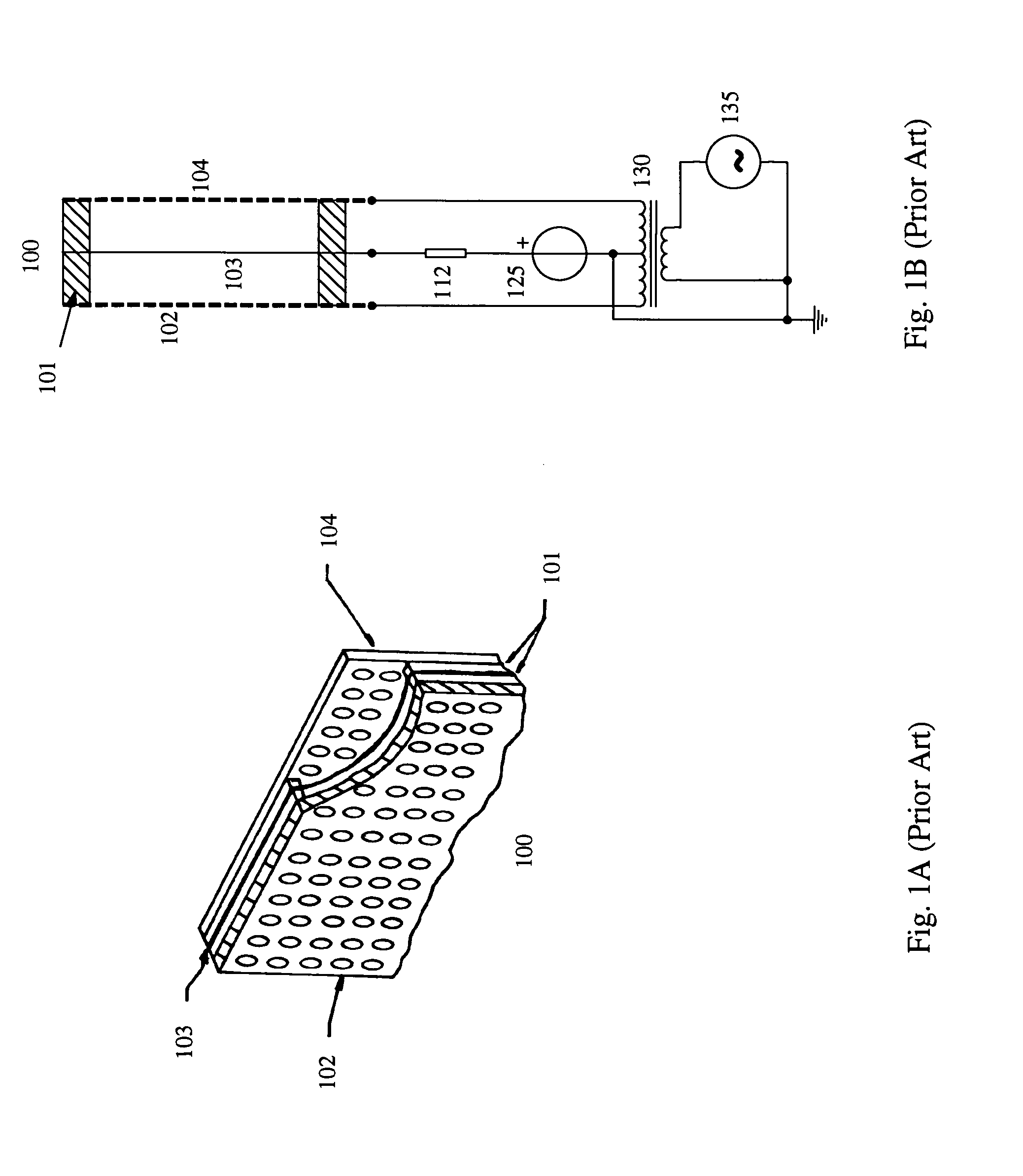
Some of the aforementioned practical limitations are: a limited sound pressure, electrical safety, a narrow dispersion of the sound wave and a natural roll off at lower frequency as a result of an acoustical short circuit between the front and back of the loudspeaker.
A disadvantage of the electrostatic loudspeaker as described in U.S. Pat. No. 7,054,456 is the need for a diaphragm with a low surface resistance in order to avoid electrical loss of the audio signal in the resistance of said diaphragm.
A further disadvantage of said electrostatic loudspeaker is that the front and back stators are connected to high DC voltages, substantially compromising electrical safety.
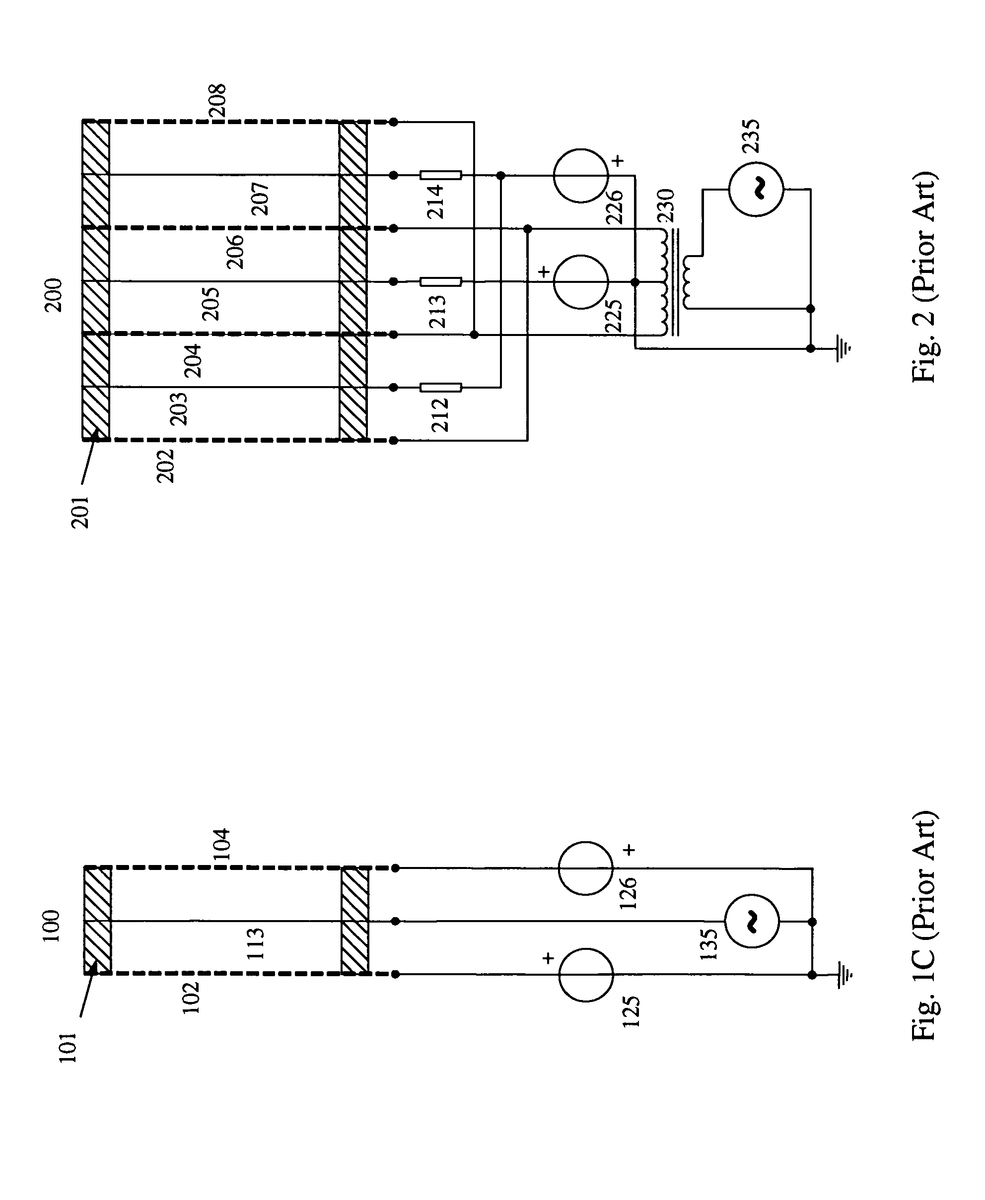
Disadvantages of the electrostatic loudspeakers described by U.S. Pat. No. 5,471,540 are an unbalance of the static forces on the diaphragms and a limited ability to reproduce higher frequencies.
A further disadvantage of said electrostatic loudspeaker is that the front and back stators are connected to high AC voltages, substantially compromising electrical safety.

Method used


Image

  • Electrostatic loudspeaker with single ended drive
  • Electrostatic loudspeaker with single ended drive
  • Electrostatic loudspeaker with single ended drive

Examples


Embodiment Construction

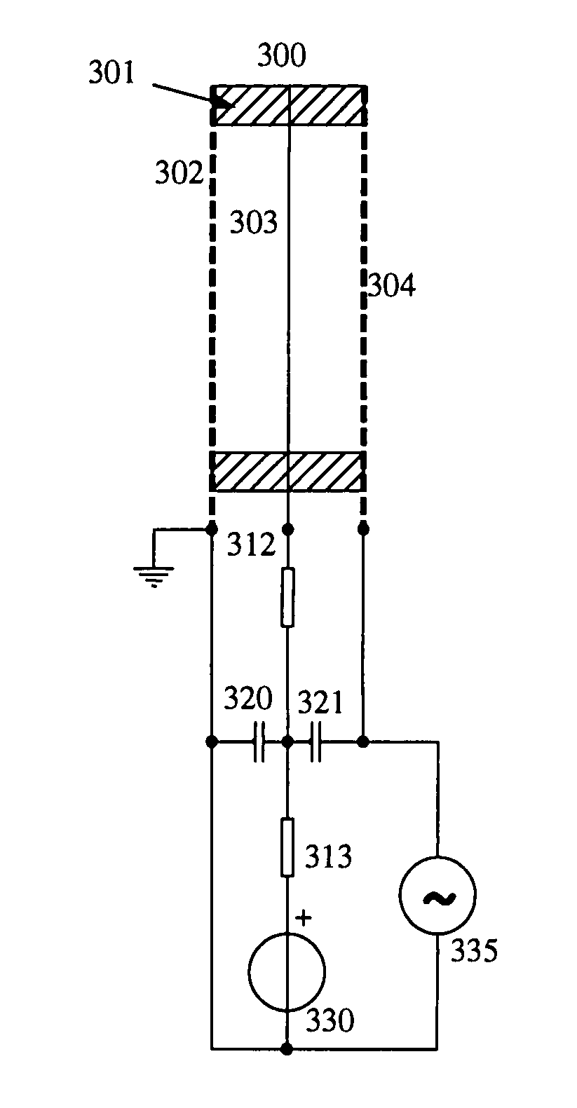
[0028]FIG. 3 illustrates a conceptual representation of a first embodiment of the invention. An electrostatic loudspeaker panel (300) includes a front stator (302), a substantially electrically conductive diaphragm (303) and a back stator (304). Said front and back stators consist of a rigid electrically conductive material with a substantially equal relative open surface area in order to pass sound wave through substantially unimpeded, established by, but not limited to for instance a homogenous perforation pattern over the entire surface area of said stators. The diaphragm consists of a thin flexible film of sufficient electrical conductivity to evenly distribute an electrical charge over its surface. The aforesaid stators and diaphragms can come in a multitude of shapes and forms, including, but not limited to flat surfaces, curved surfaces and rectangular or substantially circular shapes. The electrostatic loudspeaker panel further includes one or several insulating spacers (301...


PUM


Abstract

An electrostatic loudspeaker includes a front stator, first and second substantially conductive diaphragms, a center stator and a back stator. The front stator is connected to a safe reference potential such as earth ground. The first diaphragm, the center stator and the back stator are connected to individual positive, non equal DC bias voltages, referenced to the front stator. The second diaphragm is connected to a negative DC bias voltage. A high voltage audio signal, which is referenced to the front stator, is superimposed to the bias voltage of the center stator. The electrostatic loudspeaker can be driven by a single ended audio source. The electrostatic loudspeaker further features an improved electrical safety level.

Description

BACKGROUND OF THE INVENTION[0001]1. Field of the Invention[0002]The current invention relates to loudspeakers. More particularly it relates to electrostatic loudspeakers.[0003]2. Description of the Prior Art[0004]The majority of loudspeakers in use nowadays are of the dynamic type. The conventional dynamic loudspeaker utilizes an electromagnetic transducer system, often called the motor, to convert the electrical audio signal into a mechanical force. The electromagnetic transducer is then coupled to a diaphragm, in most cases in the form of a cone, which converts the mechanical force into an air vibration, perceived as sound. In other loudspeaker constructions the motor consists of a piezo electric transducer that drives the diaphragm.[0005]Another type of loudspeaker is the electrostatic loudspeaker, where the current invention relates to. Electrostatic loudspeakers have long been acknowledged for their excellent sound quality and lack of audible distortions and colorations. Due to...

Claims


Application Information

Patent Timeline
Patent Type & Authority Patents(United States)
IPC IPC(8): H04R3/00
CPCH04R19/02
Inventor JANSEN, ARIAN M.
Owner JANSEN ARIAN M
Learn More