
Technique for electrically connecting a generator and an exciter

a technology of electrical connection and exciter, which is applied in the direction of coupling contact member, coupling device connection, electric discharge lamp, etc., can solve the disadvantage of only requiring specific pairing of the electrical interface of the generator and the exciter, and the incompatibility of the butterfly type interface, etc., to increase the electrical safety of the connection device, increase the electrical safety, and facilitate the attachment of the connection device. simple and stable

Inactive Publication Date: 2014-10-30
SIEMENS AG
View PDF5 Cites 2 Cited by
  • Summary
  • Abstract
  • Description
  • Claims
  • Application Information

AI Technical Summary

Benefits of technology

The patent describes a connection device for electrically connecting two sets of connectors. The device has a simple design for easy connection and provides increased safety due to its insulation. The device is made of non-conducting materials for increased safety. The device is also designed to be fixed with the generators and exciters, ensuring stability during rotation. The technical effects of this patent are improved safety, ease of use, and stability of the connection device.

Problems solved by technology

A generator having the pin type interface is incompatible to be physically coupled to an exciter having the butterfly type interface for establishing an electrical connection.
Similarly, a generator having the butterfly type interface is incompatible to be physically coupled to an exciter having the pin type interface for establishing an electrical connection.
This limitation requiring only specific pairing of the electrical interface of the generator and the exciter is a disadvantage.

Method used


Image

  • Technique for electrically connecting a generator and an exciter
  • Technique for electrically connecting a generator and an exciter
  • Technique for electrically connecting a generator and an exciter

Examples


Embodiment Construction

[0042]Hereinafter, above-mentioned and other features of the present technique are described in details. Various embodiments are described with reference to the drawings, wherein like reference numerals are used to refer to like elements throughout. In the following description, for purpose of explanation, numerous specific details are set forth in order to provide a thorough understanding of one or more embodiments. It may be noted that the illustrated embodiments are intended to explain, and not to limit the invention. It may be evident that such embodiments may be practiced without these specific details.

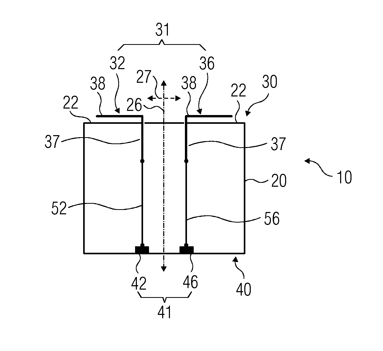
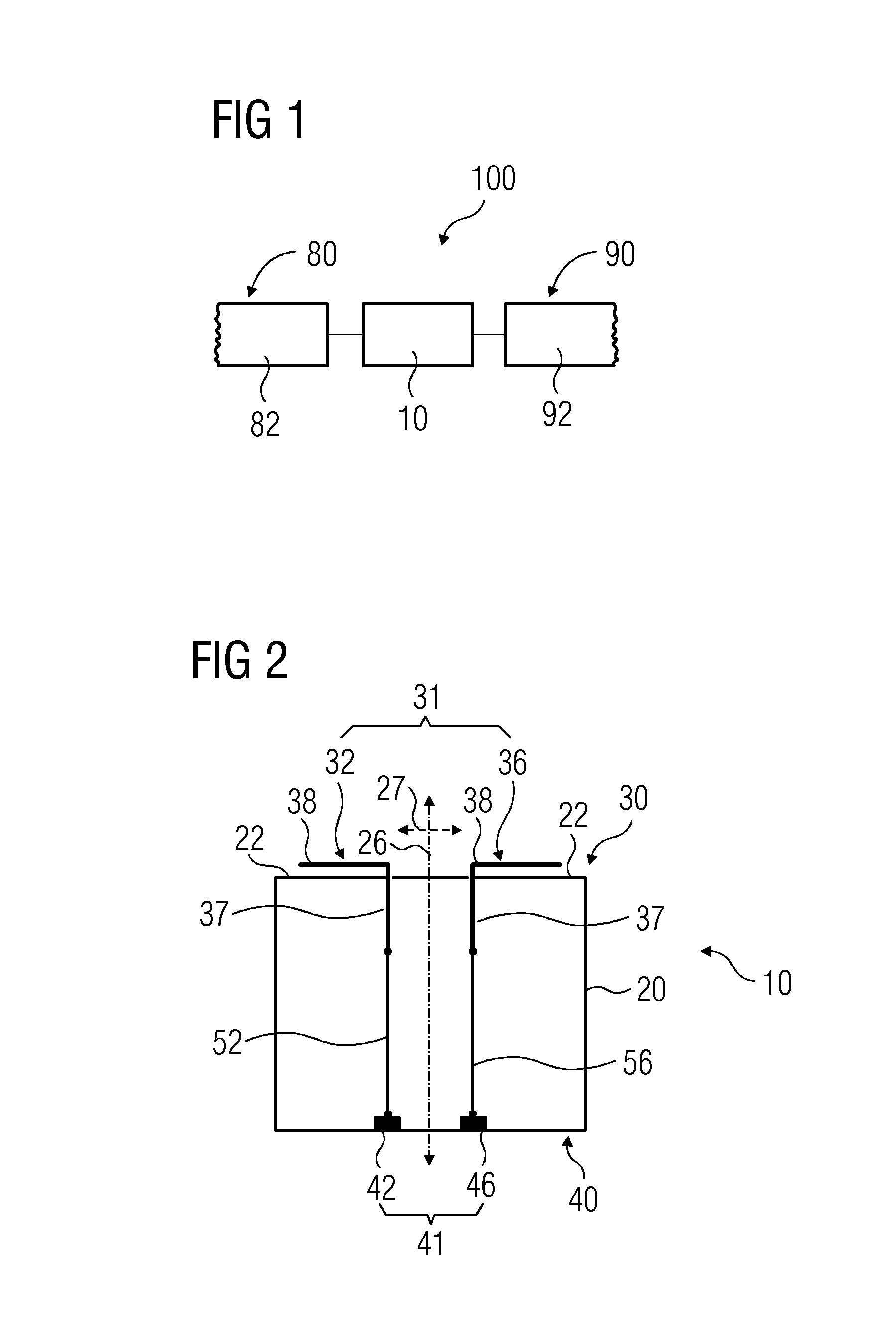
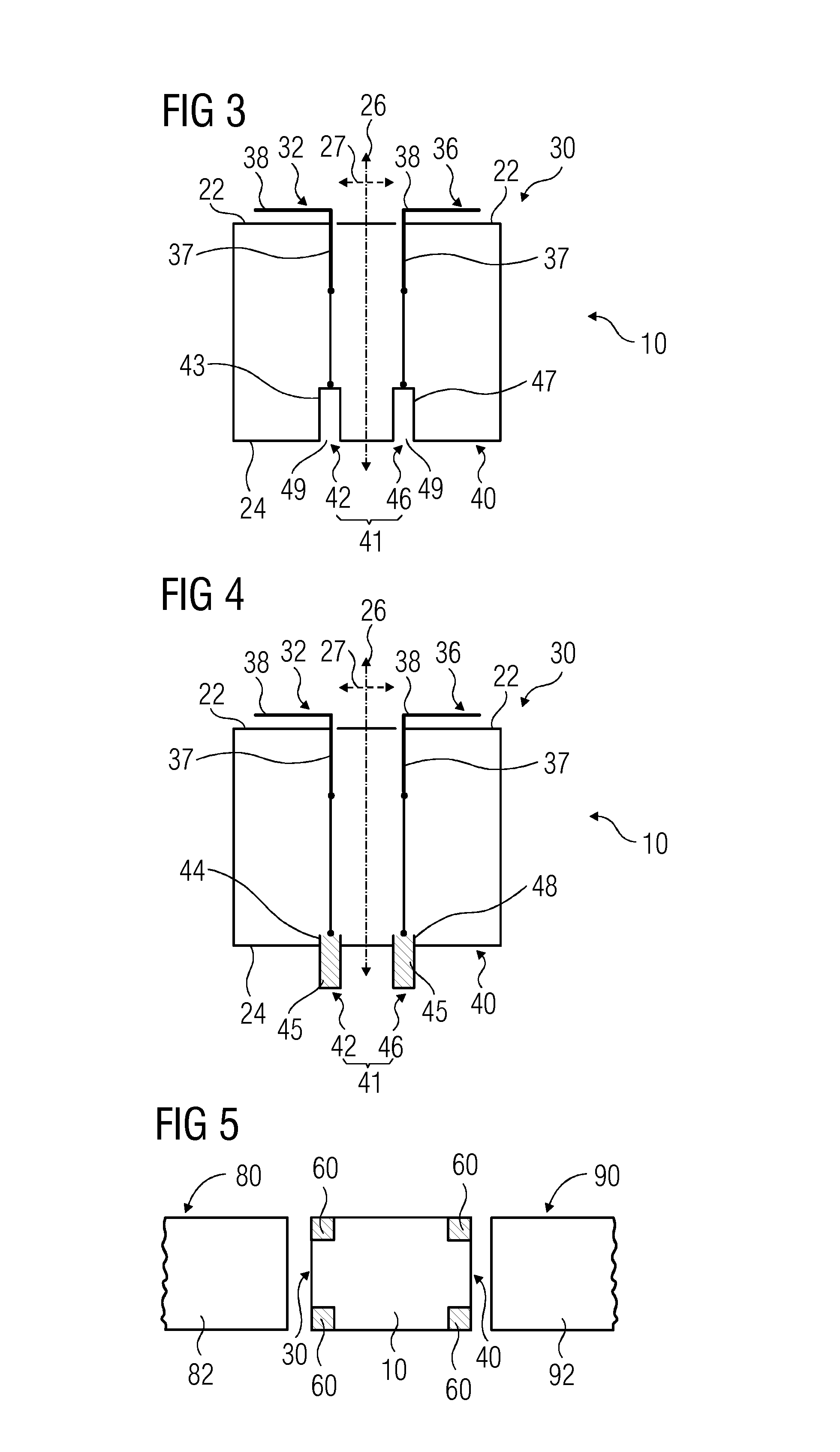
[0043]FIG. 1 is a schematic representation of a connection device 10 for electrically connecting a generator 80 and an exciter 90, in accordance with aspects of the present technique. To electrically connect the generator 80 to the exciter 90, the connection device 10 is positioned in series between a shaft 82 of the generator 80 and a shaft 92 of the exciter 90. The shaft 92 of ...


PUM


Abstract

A connection device includes a body having a first and a second end, a first connector set at the first end, and a pin type connector set at the second end. The first connector set includes a first strip element and a second strip element, which form an electrical interface of the connection device. The pin type connector set includes a first element and a second element, and thus forms another electrical interface of the connection device, different from the electrical interface formed by the first connector set. The pin type connector may be projecting pins or hollows that receive pins. The first connector set is electrically connected to the pin type connector set. Thus, the connection device is adapted for electrically connecting a generator with an exciter having incompatible electrical interfaces.

Description

CROSS-REFERENCE TO RELATED APPLICATIONS[0001]The present application claims priority of European Patent Application No. EP 13166008, filed Apr. 30, 2013, the contents of which are incorporated by reference herein.FIELD OF THE INVENTION[0002]The present invention relates to a technique for electrically connecting a generator and an exciter, and more particularly through a connection device.TECHNICAL BACKGROUND[0003]Power generation plants produce electricity by converting an energy source (e.g. fossil fuel, nuclear fusion, hydraulic heat and geothermal heat) into mechanical energy (e.g. rotation of a turbine shaft), and subsequently converting the mechanical energy into electrical energy (e.g. by the principles of electromagnetic induction). Some power generation plants, such as a turbogenerator, comprise a turbine, a generator and an exciter. Typically, the turbine, the generator and the exciter are coupled to each other in axial alignment, with the generator located between the tur...

Claims


Application Information

Patent Timeline
IPC IPC(8): H02K19/38H01R13/22H01R13/04
CPCH02K19/38H01R13/22H01R13/04
Inventor ANGERMEIER, GEARY W.BHARDWAJ, AMITBROWN, JOSHUA R.GANGISETTY, ROOPA RANIJOBE, ROBERT E.MARFIN, ALAN A.MEHRA, JATINYON, III, TERRELL H.
Owner SIEMENS AG
Learn More