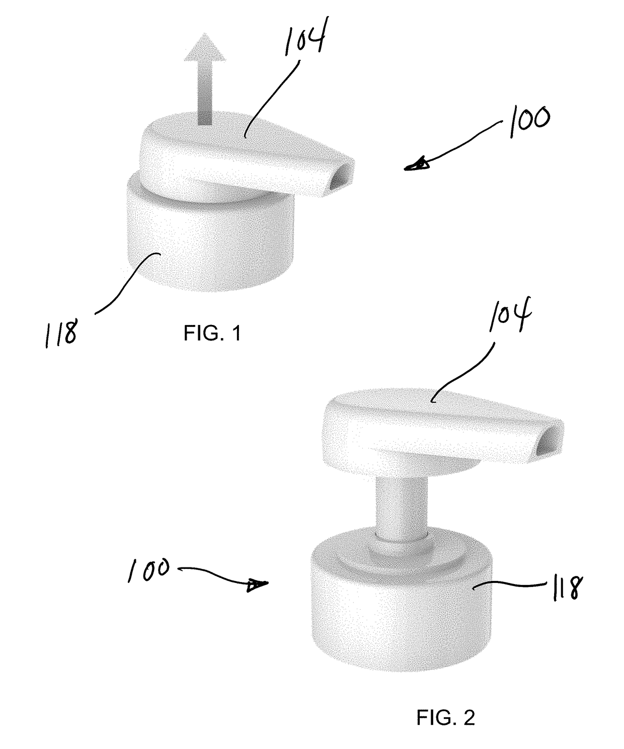
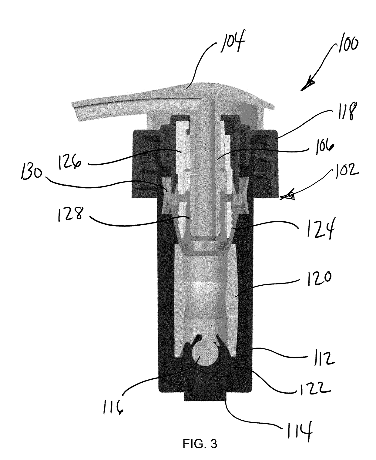
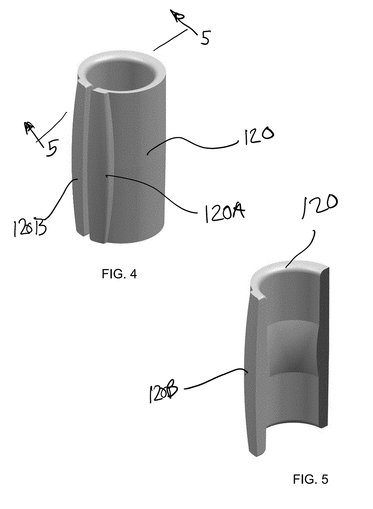
Dispensing pump with locking strcutures and methods of using the same

a technology of locking strcutures and dispensing pumps, which is applied in the direction of dispensers, single-unit devices, holders, etc., can solve the problems of reducing shipping space, affecting the recycling process, and components may not be recyclable, so as to achieve the effect of easy recycling

Active Publication Date: 2019-02-21
SILGAN DISPENSING SYST CORP
View PDF2 Cites 26 Cited by
  • Summary
  • Abstract
  • Description
  • Claims
  • Application Information

AI Technical Summary

Benefits of technology

[0005]Exemplary embodiments of a dispensing pump for liquids, viscous materials, foams, gels, etc. include a polyme

Problems solved by technology

However, the presence of the metal spring in the pump assemblies has been found to impede or slow the recycling process due to the need to separate the metal spring fro

Method used


Image

  • Dispensing pump with locking strcutures and methods of using the same
  • Dispensing pump with locking strcutures and methods of using the same
  • Dispensing pump with locking strcutures and methods of using the same

Examples


exemplary embodiment 200

[0065]As illustrated in FIGS. 16 and 16A, in another exemplary embodiment 200, the piston stem plug 228 includes an outwardly extending snap bead 252 on a lower peripheral edge thereof. During shipping, the snap bead 252 is engaged with a lower peripheral edge of the guide tube 226 to retain the piston stem plug 228 and piston stem 206 in the locked position. The snap bead 252 increases the unlocking force required to pull the dispensing head 204 upwardly to the deployed position, i.e. the added force required to force the snap bead 252 over the lower peripheral edge of the guide tube 226.

exemplary embodiment 300

[0066]Turning to FIGS. 17, 18 and 18A, in another exemplary embodiment 300, the piston plug 328 may include a sealing rim 354 which provides a slightly higher level of friction within the guide tube 326 for better retention in the retracted position. This assembly 300 may also be paired with a frangible tear strip 356 engaged between the closure ring 318 and the dispensing head 304 to prevent accidental deployment of the dispensing head 304. Once the tear strip 356 is removed, the dispensing head 304 may be more easily pulled upward to the deployed or extended position.

[0067]Another exemplary embodiment 400 is illustrated in FIGS. 19 and 20. The pump assembly 400 generally comprises a dispensing head 404, an accumulator cup 412 and closure ring 418, spring assembly 408 with spring element 420 and piston seal 430 as previously described. A locking structure 410 may comprise a slotted tubular band 460 captured between the closure ring 418 and the dispensing head 404. The dispensing he...


PUM

PropertyMeasurementUnit
Tensile propertiesaaaaaaaaaa
Plasticityaaaaaaaaaa
Frictionaaaaaaaaaa

Abstract

A dispensing pump includes a spring assembly and a locking arrangement to prevent the dispensing head from being deployed and/or actuated during shipment, stocking and pre-purchase handling. The dispensing pump includes a pump base, and a dispensing head having a piston stem. The spring assembly includes a slotted tubular spring element and first and second loading cones received at opposing ends of the slotted tubular spring element. Various locking arrangements may include interacting rotatable lugs provided between the dispensing head and the pump base, snap beads to retain the piston and dispensing head in a secured shipping position, and recyclable locking rings disposed between the dispensing head and pump base which prevent an active dispensing head from being actuated.

Description

CROSS-REFERENCE TO RELATED APPLICATIONS[0001]This application is a continuation-in-part of U.S. application Ser. No. 15 / 861,108, filed Jan. 3, 2018, the entire contents of which is incorporated herein by reference.BACKGROUND OF THE DISCLOSURE(1) Field of the Invention[0002]The present invention generally relates to dispensing pumps for liquids, viscous flowable materials, foams, gels, etc. and more particularly to a dispensing pump with recyclable spring and locking components.(2) Description of Related Art[0003]Dispensing pumps for various liquids, lotions, foams, gels, etc. are known in the art. They generally comprise a body portion which is seated on the neck of a container, a co-acting nozzle portion which slides relative to the body portion, and a spring structure which biases the co-acting nozzle portion to its normal rest position. To dispense the material in the container, the user manually depresses the nozzle which forces the material from the inside of the body portion o...

Claims


Application Information

Patent Timeline
IPC IPC(8): B05B11/00
CPCB05B11/306B05B11/105B05B11/106B05B11/1047B05B11/1059B05B11/1067B05B11/1076B05B11/1077F16F1/025F16F2234/02F16F2236/025F16F2230/36F16F2236/04A47K5/1205B05B11/0037F16F1/36F16F1/3605F16F1/373F16F1/3732F16F1/377F16F1/44B05B11/1001B05B11/1023B05B11/1074
Inventor DEMAN, EELCO H.JENNETTE, JACQUELINECHOI, DANIEL
Owner SILGAN DISPENSING SYST CORP
Why Eureka
Try Eureka