

Device for controlling at least one valve in an internal combustion engine
- Summary
- Abstract
- Description
- Claims
- Application Information
AI Technical Summary
Benefits of technology
Problems solved by technology
Method used
Image

Examples
Embodiment Construction
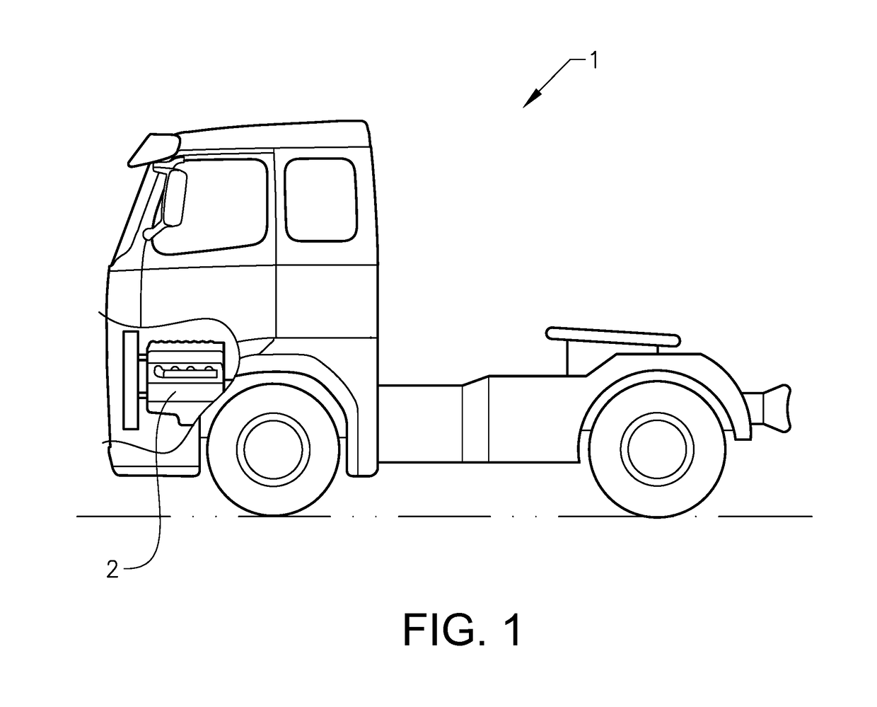
[0061]FIG. 1 shows a vehicle in the form of a truck 1 in a partly cut side view. The truck 1 comprises an internal combustion engine 2 in the form of a diesel engine.
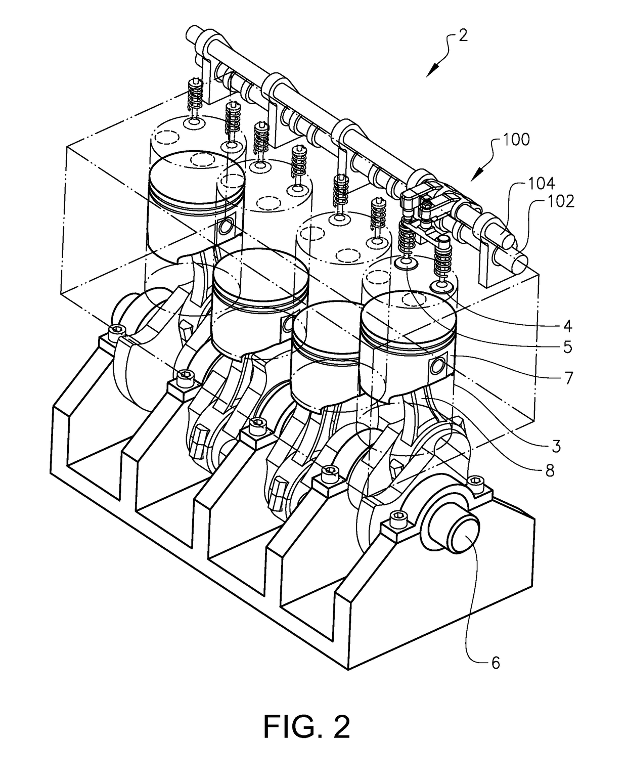
[0062]FIG. 2 is a schematic perspective view of a first embodiment of the engine 2. The engine 2 comprises at least one cylinder 3 and in the shown example a plurality of cylinders. More specifically, the engine 2 comprises four cylinders in the shown example. However, the engine may be provided with any number of cylinders, such as six cylinders. The engine 2 comprises a cylinder 3 provided with at least one intake valve and at least one exhaust valve 4,5. More specifically, the cylinder 3 is provided with two intake valves and two exhaust valves 4,5. Further, the engine 2 comprises a crankshaft 6. The crankshaft 6 is connected to a piston 7 in the cylinder 3 via a connecting rod 8 for transmitting a downward motion of the piston to a rotating motion of the crankshaft. Further, the engine 2 comprises a valve actuation ...
PUM
 Abstract
Description
Claims
Application Information