Supercharge Your Innovation With Domain-Expert AI Agents!

Entrance and exit chip rings for balancing broach forces

Active Publication Date: 2019-02-28
RAYTHEON TECH CORP
View PDF13 Cites 0 Cited by
  • Summary
  • Abstract
  • Description
  • Claims
  • Application Information

AI Technical Summary

Benefits of technology

The patent describes a system and method for creating a ring-to-ring assembly of components. The system includes two chip rings and a component between them. The chip rings have through slots that are coaxial with a slot axis at a non-zero angle relative to the component's surface. The method involves using a broach tool to form slots in the chip rings and then in the component. The technical effects include a more efficient and precise way to create ring-to-ring assemblies for a wide range of components.

Problems solved by technology

The deflection potentially causes dimensional errors or quality problems in the slot 206.

Method used


Image

  • Entrance and exit chip rings for balancing broach forces
  • Entrance and exit chip rings for balancing broach forces
  • Entrance and exit chip rings for balancing broach forces

Examples


Embodiment Construction

[0019]It is noted that various connections are set forth between elements in the following description and in the drawings (the contents of which are incorporated in this specification by way of reference). It is noted that these connections are general and, unless specified otherwise, may be direct or indirect and that this specification is not intended to be limiting in this respect. A coupling between two or more entities may refer to a direct connection or an indirect connection. An indirect connection may incorporate one or more intervening entities or a space / gap between the entities that are being coupled to one another.

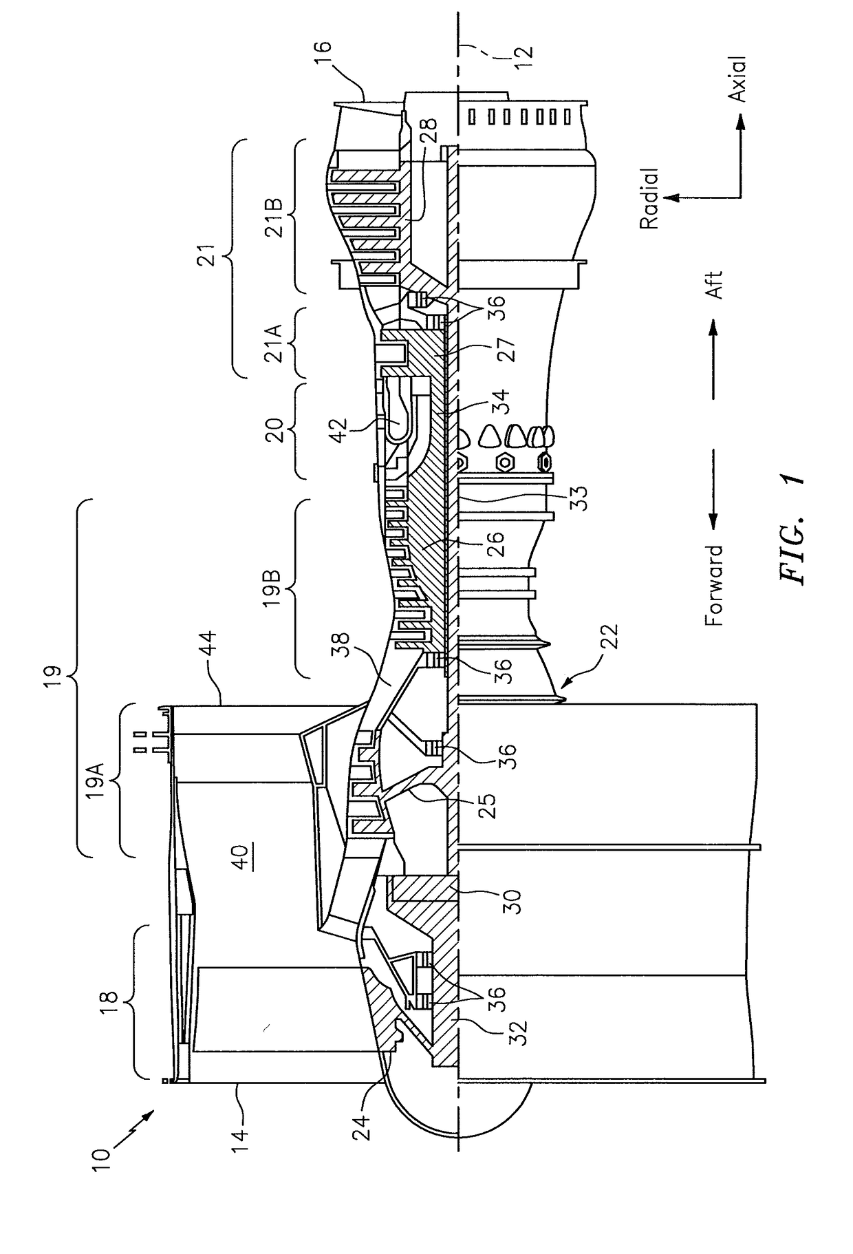
[0020]Aspects of the disclosure may be applied in connection with a gas turbine engine. FIG. 1 is a side cutaway illustration of a geared turbine engine 10. This turbine engine 10 extends along an axial centerline 12 between an upstream airflow inlet 14 and a downstream airflow exhaust 16. The turbine engine 10 includes a fan section 18, a compressor section 1...


PUM

PropertyMeasurementUnit
Angleaaaaaaaaaa
Angleaaaaaaaaaa

Abstract

Aspects of the disclosure are directed to a first chip ring that includes a first through slot, a second chip ring that includes a second through slot, and a component disposed between the first chip ring and the second chip ring that includes a component through slot, where the first, second and component through slots are coaxial along a slot axis this is oriented at a non-zero valued angle relative to a planar surface of the component facing at least one of the first and second chip rings.

Description

BACKGROUND[0001]Gas turbine engines, such as those which power aircraft and industrial equipment, employ a compressor to compress air that is drawn into the engine and a turbine to capture energy associated with the combustion of a fuel-air mixture. The compressor and the turbine include disks. The disks include slots that seat blades. A slot in a disk holds a blade in place and resists centrifugal forces that would otherwise cause the blade to become detached from the disk.[0002]Referring to FIG. 2A, a system 200 for forming a slot 206 in a disk 212 is shown. In particular, a broach tool 218 is used to machine the slot 206 in the disk 212. The broach tool 218 is initially applied to the disk 212 at an entrance / surface 212a of the disk 212. Continued application of the broach tool 218 (e.g., teeth 218a of the broach tool 218) to the disk 212 causes material of the disk 212 to be removed; this removal of material forms the slot 206 in the disk 212.[0003]Referring to FIG. 2B, the slot...

Claims


Application Information

Patent Timeline
IPC IPC(8): B23D43/02B23D43/00
CPCB23D43/02B23D43/005F01D5/02F01D5/3007B23D2043/025F01D15/12F05D2220/32F05D2230/10F05D2300/133F04D29/322B23D39/00Y10T407/1685Y10T409/40595B23D37/22
Inventor FRISK, KENNETH A.ALI, STEPHENNORAAS, RYAN B.KOUNTANYA, RAJAKETSCHKE, LAUREN
Owner RAYTHEON TECH CORP
Features
  • R&D
  • Intellectual Property
  • Life Sciences
  • Materials
  • Tech Scout
  • Unparalleled Data Quality
  • Higher Quality Content
  • 60% Fewer Hallucinations
Learn More