
Vehicle

a technology for vehicles and levers, applied in the field of vehicles, can solve the problems of increasing the shift load required for the driver to operate the shift lever, the driver's operation force is lost by the component force in the right-left direction, and the operation force is not efficiently transmitted to the switching. , to achieve the effect of improving the motion performance of the vehicle, reducing the proportion of the driver's shifting operation force lost by the component force in the right-left direction, and not having to increase the strength of the shift rod

Active Publication Date: 2019-02-28
YAMAHA MOTOR CO LTD
View PDF0 Cites 2 Cited by
  • Summary
  • Abstract
  • Description
  • Claims
  • Application Information

AI Technical Summary

Benefits of technology

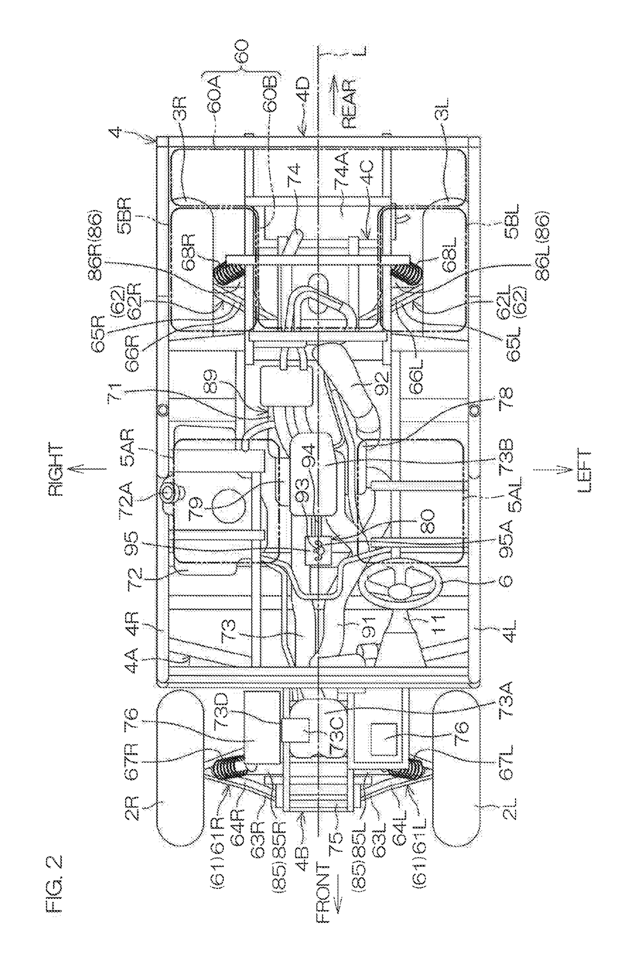
The present invention relates to a vehicle design that includes a continuously variable transmission and a shiftable transmission located on the same side of the engine. A switching lever is located near the continuously variable transmission and can be easily operated by the driver from either seat. The vehicle also includes a fuel tank that does not interfere with the maintenance of the continuously variable transmission. The technical effect is that the vehicle design allows for efficient and easy maintenance of the continuously variable transmission without having to remove the fuel tank.

Problems solved by technology

It was discovered that the shifting operation force is thus not transmitted efficiently to the switching lever and an operation sensation therefore becomes poor.
The shifting operation force must therefore include the force that is lost as the component force in the right-left direction in addition to the force required for actuation of the switching lever, and therefore a shift load required for the driver to operate the operation lever increases and an operation feeling therefore may become poor.

Method used


Image

  • Vehicle
  • Vehicle
  • Vehicle

Examples


Embodiment Construction

[0031]In the preferred embodiments of the present invention described below, front-rear, right-left, and up-down are directions defined based on a viewpoint of a driver sitting on a seat of a vehicle and facing a steering wheel. The right-left direction is a vehicle width direction of the vehicle. Also, the description shall be provided based on a state where the vehicle is on a horizontal plane.

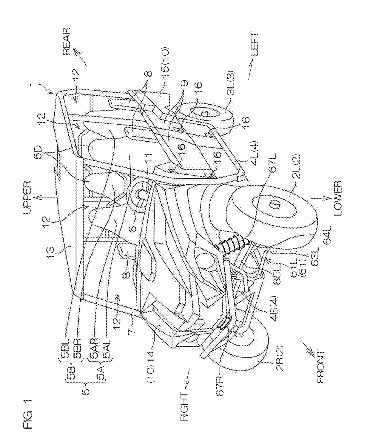
[0032]FIG. 1 is a schematic perspective view of the vehicle 1 according to a preferred embodiment of the present invention. The vehicle 1 is preferably a utility vehicle and more specifically is preferably a four-wheel drive, all-terrain vehicle that is called a recreational off-road vehicle and travels through forests, deserts, etc.

[0033]The vehicle 1 includes a pair of right and left front wheels 2, a pair of right and left rear wheels 3, a frame 4, at least one seat 5, a steering wheel 6, a roll cage 7, bolsters 8, doors 9, and a body panel 10.

[0034]The pair of right and left front wheels...


PUM


Abstract

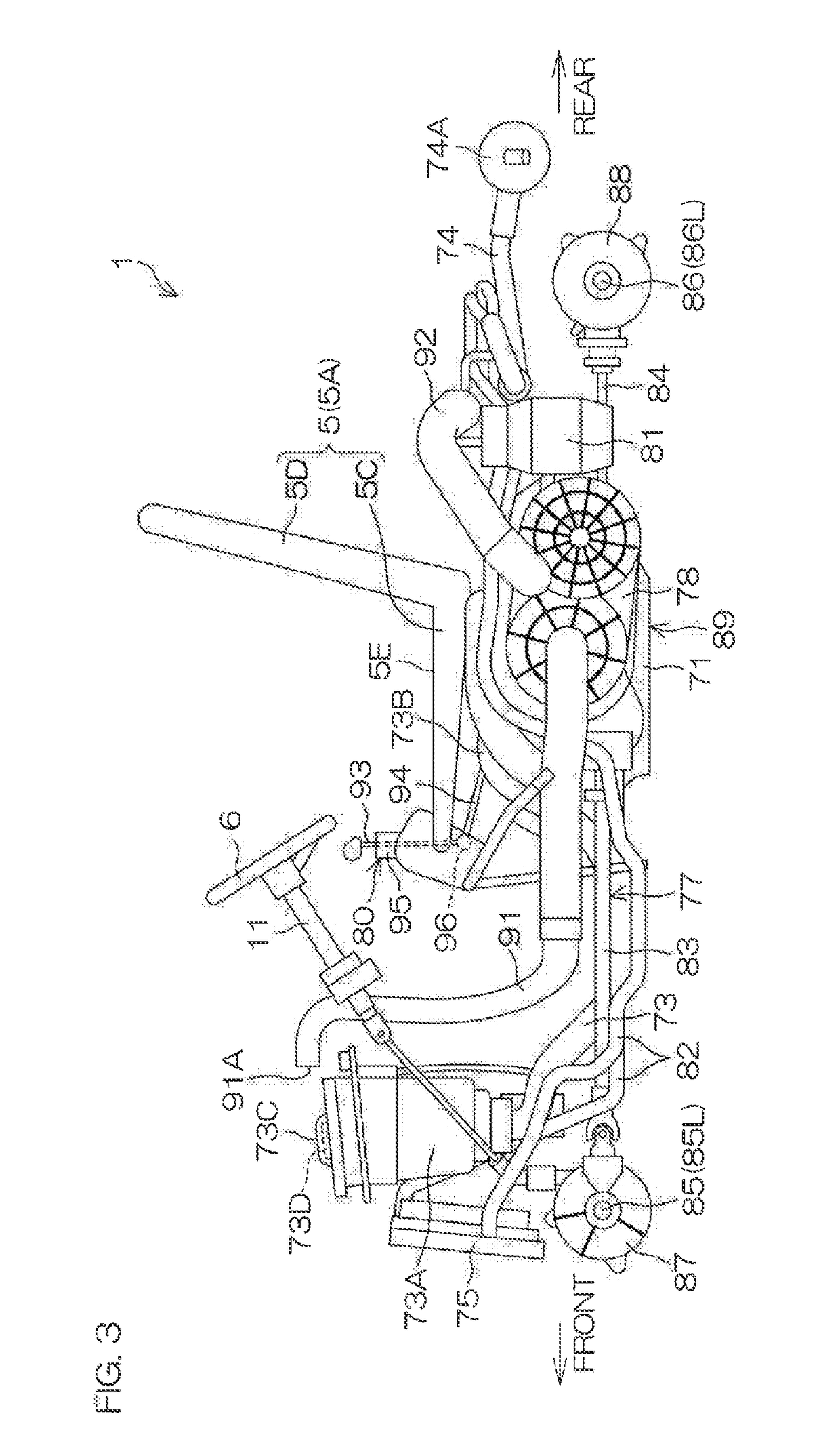
A vehicle includes an engine, a continuously variable transmission, a shiftable transmission, a switching lever, a shift rod, and an operation lever. The continuously variable transmission is located at a side of the engine. The shiftable transmission is located on the same side as the engine in a right-left direction with respect to the continuously variable transmission. The switching lever is located on the same side as the continuously variable transmission with respect to a center of the shiftable transmission in the right-left direction, and inputs a shifting operation force into the shiftable transmission. The shift rod is linked to the switching lever. The operation lever is operated by a driver seated on the seat to shift the shiftable transmission, and is linked to the shift rod.

Description

CROSS REFERENCE TO RELATED APPLICATIONS[0001]This application claims the benefit of priority to Japanese Patent Application No. 2017-159748 filed on Aug. 22, 2017. The entire contents of this application are hereby incorporated herein by reference.BACKGROUND OF THE INVENTION1. Field of the Invention[0002]The present invention relates to a vehicle that includes a shiftable transmission, an operation lever shifted by a driver, and a shift rod connecting the shiftable transmission and the operation lever.2. Description of the Related Art[0003]A left-hand drive vehicle described in U.S. Pat. No. 8,381,855 includes a driver's seat and a passenger's seat that are aligned right and left, and an engine unit located between the seats. The engine unit includes an engine main body and a continuously variable transmission located to the left of the engine main body. Shifting is performed when a driver seated on the driver's seat operates an operation lever located adjacent to the right of the d...

Claims


Application Information

Patent Timeline
Patent Type & Authority Applications(United States)
IPC IPC(8): B60K23/02B60N2/01B60K5/00B60K17/04B60K15/03
CPCB60K23/02B60N2/01B60K5/00B60K17/04B60K15/03B60K17/34B60K5/02B60K17/08B60K20/04
Inventor OBA, SHIGEAKINAKAGAKI, SEIJIFUJIMOTO, HIROYUKIHAYASHI, TOMOYUKI
Owner YAMAHA MOTOR CO LTD
Learn More