
Supplemental turning function-equipped hub unit and vehicle

Active Publication Date: 2020-04-23
NTN CORP
View PDF0 Cites 2 Cited by
  • Summary
  • Abstract
  • Description
  • Claims
  • Application Information

AI Technical Summary

Benefits of technology

The present invention is a hub unit that improves the motion performance of a vehicle by providing supplemental turning in both left and right wheels based on travel conditions. This results in better travel stability and increased fuel economy. The hub unit is simple and strong, and can be used in vehicles to provide this improved performance.

Problems solved by technology

In such a case, however, the turning angle of the outer ring becomes excessively large in a low-speed range because the difference in turning angles of the left and right wheels is insufficient, whereas the turning angle of the inner ring becomes excessively large in a high-speed range.
Thus, when distribution of a tire lateral force becomes unnecessarily unbalanced between inner and outer rings, travel resistance may be deteriorated, thereby causing worsening of fuel economy and early wear of the tire.
Further, there is a problem that smooth cornering is deteriorated because the inner and outer rings cannot not be effectively used.
Although the mechanisms disclosed in Patent Documents 1 and 2 can change the steering geometries, they have the following problems.
It is extremely difficult to provide a motor actuator which can provide such a large force that the vehicle geometries can be changed in such a part, due to space constraints.
Since two motors are used in Patent Document 2, the increased number of the motors results in increased costs and makes it complicated to control.
In addition, since a hub bearing is supported in a cantilever manner with respect to a turning shaft, rigidity is reduced, and a steering geometry may be changed due to generation of excessive turning acceleration G Where a speed reduction gear is provided on the turning shaft, a large power is required.
However, where a larger motor is used to obtain such a large motor, it is difficult to dispose the entire motor in an inner peripheral part of a wheel.
Where a speed reduction gear having a high reduction ratio is provided, responsibility is deteriorated.
As discussed above, a mechanism having a conventional supplemental turning function is intended to arbitrarily change a toe angle and a camber angle of a tire in a vehicle and thus has a complicated structure.
In addition, it is difficult to ensure rigidity, and it is necessary to make the mechanism large in order to ensure rigidity, resulting in an increased weight.
However, such a device tends to be unable to perform independent turning of the left and right rear wheels and / or toe angle adjustment.
In addition, where the device is capable of performing independent turning, the device may have a complicated configuration and / or may not be sufficiently strong.

Method used


Image

  • Supplemental turning function-equipped hub unit and vehicle
  • Supplemental turning function-equipped hub unit and vehicle
  • Supplemental turning function-equipped hub unit and vehicle

Examples


first embodiment

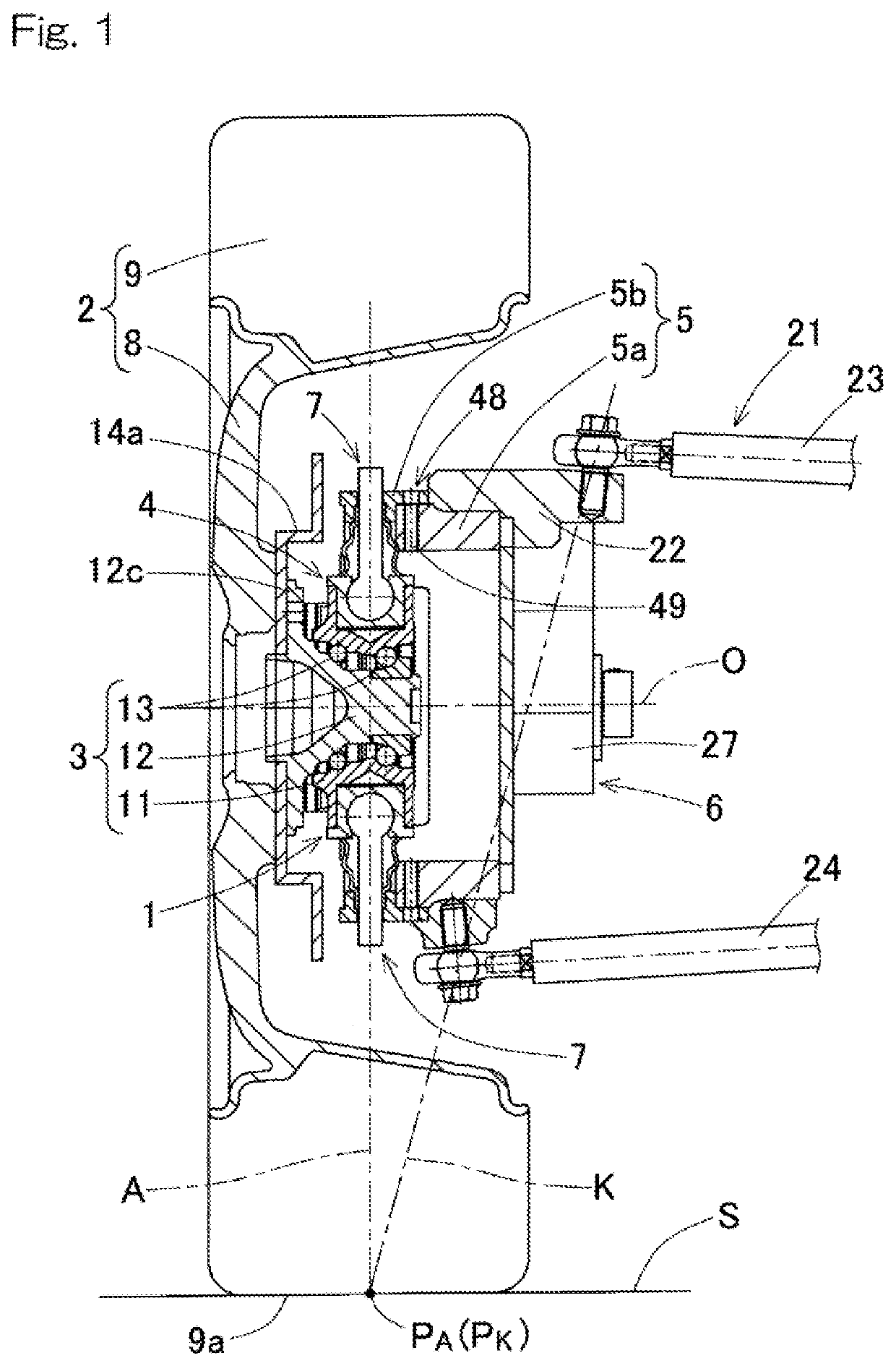
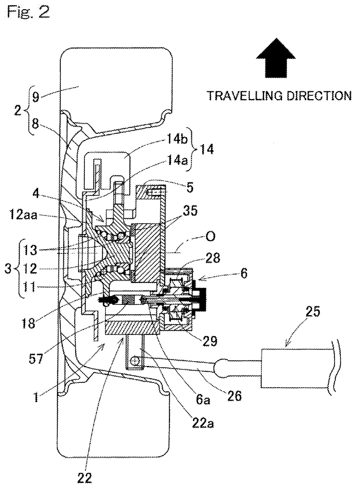
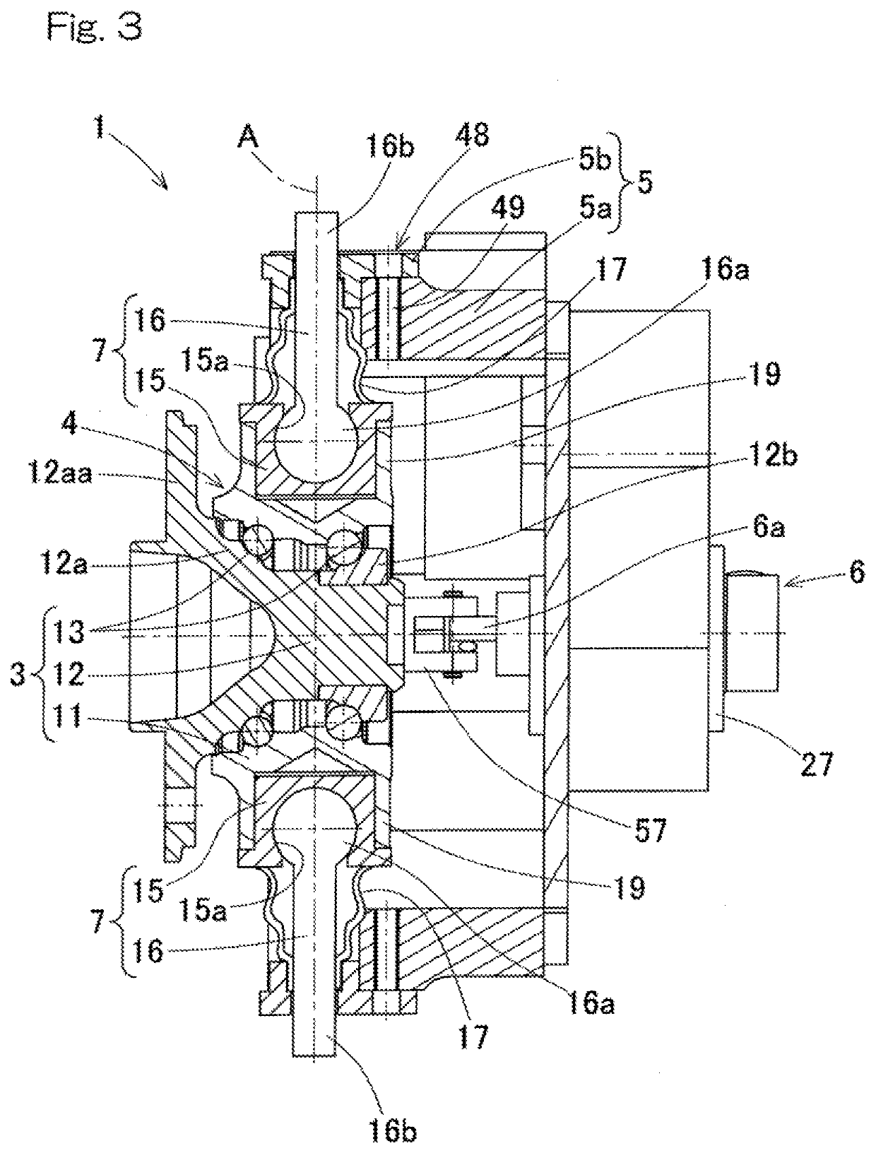
[0047]the present invention will be described with reference to the drawings. As shown in FIG. 1, a supplemental turning function-equipped hub unit 1 includes: a hub unit body 4 including a hub bearing 3 for supporting a wheel 2; a unit support member 5; and a supplemental turning actuator 6. The hub unit body 4 is supported by the unit support member 5 through rotation-permitting support components 7, 7 at two portions or upper and lower portions thereof so as to be rotatable about a supplemental turning axis A extending in a vertical direction or an up-and-down direction. The supplemental turning axis A is different from a rotation axis O of the wheel 2 and from a king pin axis K of main steering. The wheel 2 includes a wheel body 8 and a tire 9.

[0048]The supplemental turning function-equipped hub unit 1 of this embodiment is mounted to a knuckle 22 of a front wheel that is a turning wheel. Specifically, as shown in FIG. 15, the supplemental turning function-equipped hub unit 1 is...

second embodiment

[0078]FIG. 8 to FIG. 12 show the present invention. In this embodiment, a rotation-permitting support component 7A in the form of a tapered roller bearing is used, instead of the rotation-permitting support component 7 in the form of the spherical sliding bearing as shown in FIG. 1. As shown in FIG. 10, attachment shaft parts 19A each in the form of a trunnion shaft are provided on the outer ring 11 of the hub bearing 3 so as to protrude. Two of the attachment shaft parts 19A are provided on the upper and lower portions of the outer ring 11. Each of the attachment shaft part 19A in the form of the trunnion shaft has an outer periphery, to which an inner ring 15A of the rotation-permitting support component 7A in the form of the tapered roller bearing is fitted. An outer ring 16A of the rotation-permitting support component 7A is fitted to a fitting hole 38 provided in a unit support member 5A.

[0079]The upper rotation-permitting support component 7A is formed with a male thread porti...


PUM


Abstract

A supplemental turning function-equipped hub unit includes: a hub unit body including a hub bearing; and a unit support member configured to be mounted through a suspension device, the unit support member supporting the hub unit body through rotation-permitting support components at two upper and lower portions of the hub unit body such that the hub unit body is rotatable about a supplemental turning axis. A supplemental turning force receiving part is provided on a side part of the hub unit body, which part is configured to receive a force that causes the hub unit body to rotate about the supplemental turning axis.

Description

CROSS REFERENCE TO THE RELATED APPLICATION[0001]This application is a continuation application, under 35 U.S.C. § 111(a) of international patent application No. PCT / JP2018 / 023592, filed Jun. 21, 2018, which claims priority to Japanese patent application No. 2017-122997, filed Jun. 23, 2017, the entire disclosures of all of which are herein incorporated by reference as a part of this application.BACKGROUND OF THE INVENTIONField of the Invention[0002]The present invention relates to a supplemental turning function-equipped hub unit having a function of performing additional turning to turning performed by a steering device and / or performing supplemental turning, such as rear wheel turning, and to a vehicle having such a supplemental turning function-equipped hub unit.Description of Related Art[0003]In general, vehicles, such as automobiles, include a steering wheel mechanically connected with a steering device, the steering device having opposite ends connected to left and right wheel...

Claims


Application Information

Patent Timeline
IPC IPC(8): B62D5/04B62D7/18F16C19/18
CPCB62D7/18B62D5/0427F16C2326/02F16C19/187B62D17/00B60G7/006B60G3/20B60G2200/144B60G2202/44
Inventor OOBA, HIROKAZUISHIKAWA, TOMOMINISHIKAWA, KENTAROUTSUNOMIYA, SATOSHIOHATA, YUSUKEIGI, TAISUKEISHIHARA, NORIO
Owner NTN CORP
Learn More