Wireless power feeding system, wireless power transmitter, and wireless power receiver
a technology of wireless power transmission and wireless power, which is applied in the direction of transmission, battery data exchange, exchange data chargers, etc., can solve the problems of complex and sophisticated control, inability to provide reliable signal transmission, and inability to achieve reliable signal transmission, etc., to achieve high-quality signal transmission and high-quality signal transmission.
- Summary
- Abstract
- Description
- Claims
- Application Information
AI Technical Summary
Benefits of technology
Problems solved by technology
Method used
Image

Examples
first embodiment
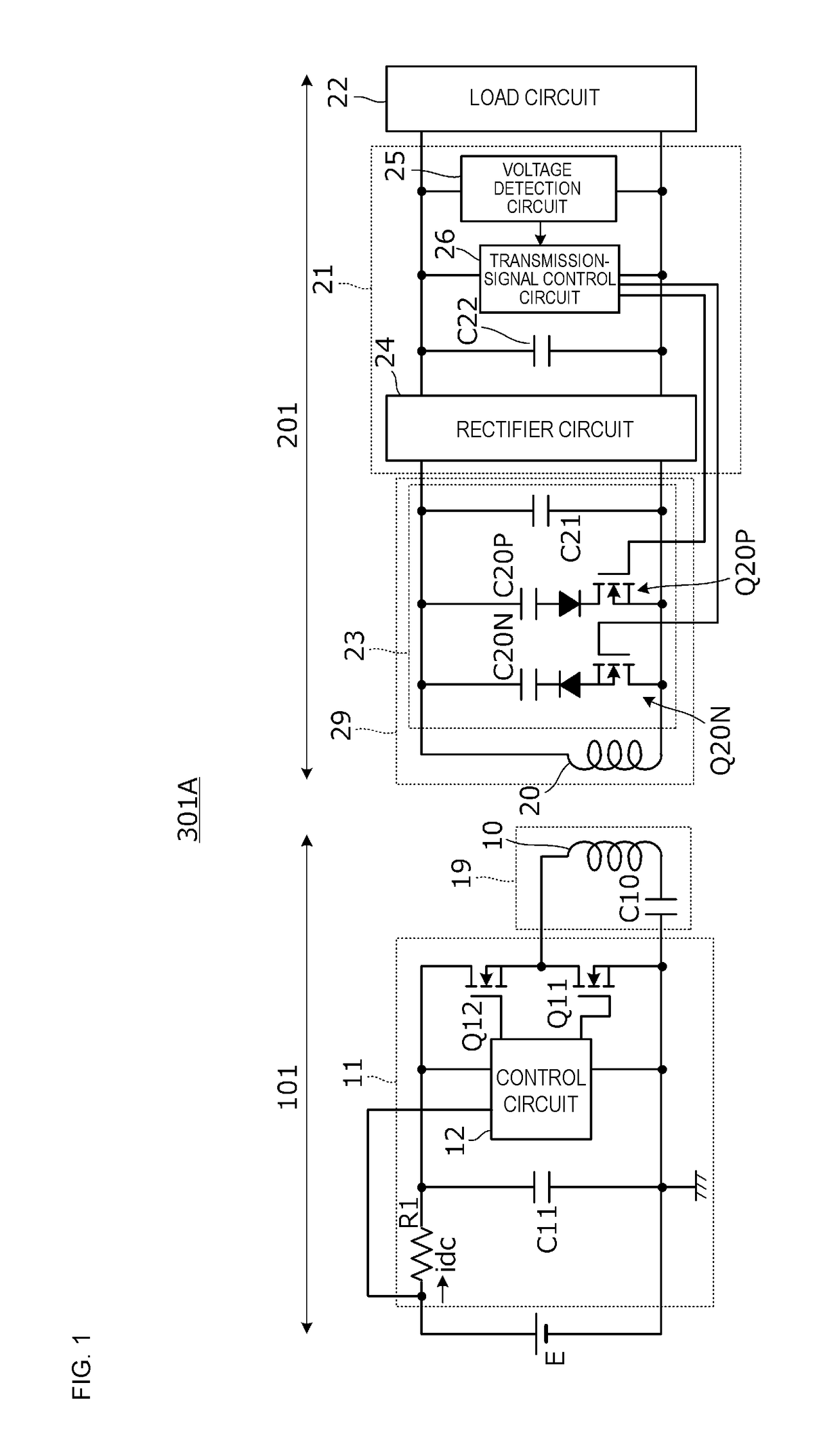
[0039]FIG. 1 is a circuit diagram according to a first embodiment, illustrating a wireless power transmitter, a wireless power receiver, and a wireless power feeding system including the wireless power transmitter and the wireless power receiver.
[0040]A wireless power feeding system 301A includes a wireless power transmitter 101, and a wireless power receiver 201. The wireless power transmitter (to be referred to as simply “transmitter” hereinafter) 101 has a transmitting resonant circuit 19, and a transmitting circuit 11. The transmitting resonant circuit 19 includes a transmitting coil 10, and a resonant capacitor C10. The transmitting circuit 11 supplies high-frequency power to the transmitting coil 10. The wireless power receiver (to be referred to as simply “receiver” hereinafter) 201 has a receiving coil 20, a receiving resonant circuit 29, a receiving circuit 21, and a load circuit 22. The receiving coil 20 electromagnetically couples to the transmitting coil 10. The receivin...
second embodiment
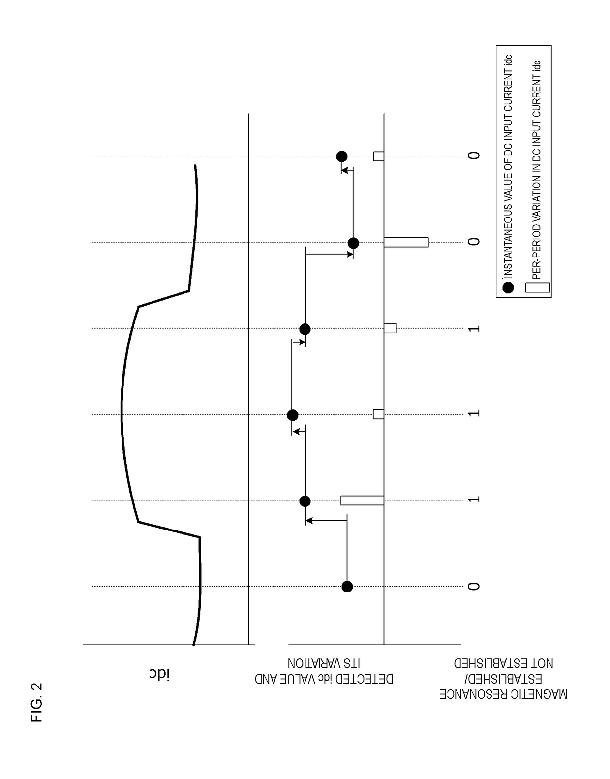
[0070]The following description of a second embodiment will be directed to a wireless power feeding system that demodulates a transmission signal based on a quantity related to a resonant voltage generated in the resonant circuit including the transmitting coil.
[0071]FIG. 9 is a circuit diagram according to the second embodiment, illustrating a wireless power transmitter, a wireless power receiver, and a wireless power feeding system including the wireless power transmitter and the wireless power receiver.
[0072]A wireless power feeding system 302A includes the transmitter 101 and the receiver 201. The transmitter 101 includes the transmitting coil 10, and the transmitting circuit 11 that supplies high-frequency power to the transmitting coil 10. The receiver 201 includes the receiving coil 20 that electromagnetically couples to the transmitting coil 10, the receiving circuit 21 that converts high-frequency power received by the receiving coil 20 into DC power, and the load circuit 2...
third embodiment
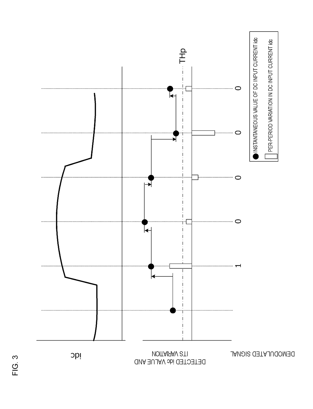
[0081]A third embodiment represents an example of a wireless power feeding system that performs demodulation through comparison of two thresholds with the amount of variation in a variable that varies in accordance with whether the electromagnetic resonance condition is established.
[0082]The circuit diagram of the wireless power feeding system according to the third embodiment is identical to the circuit diagram according to the first embodiment illustrated in FIG. 1.
[0083]FIG. 11 illustrates the relationship between establishment / non-establishment of an electromagnetic resonance condition and variation in DC input current idc. The vertical dashed lines in FIG. 11 represent sampling timing. Since the DC input current idc is a current supplied from the input power source E to the transmitting circuit 11, its value is greater when electromagnetic resonant coupling is established than when electromagnetic resonant coupling is not established. In FIG. 11, “signal binarized with THp” rep...
PUM
 Abstract
Description
Claims
Application Information
 - R&D
- Intellectual Property
- Life Sciences
- Materials
- Tech Scout
- Unparalleled Data Quality
- Higher Quality Content
- 60% Fewer Hallucinations
Browse by: Latest US Patents, China's latest patents, Technical Efficacy Thesaurus, Application Domain, Technology Topic, Popular Technical Reports.
© 2025 PatSnap. All rights reserved.Legal|Privacy policy|Modern Slavery Act Transparency Statement|Sitemap|About US| Contact US: help@patsnap.com