Supercharge Your Innovation With Domain-Expert AI Agents!

Fly swatter

a technology of flying swatter and swatter body, which is applied in the field of flying swatter, can solve the problem of less time, and achieve the effect of easy and inexpensive production

Active Publication Date: 2019-03-21
LEBERER THOMAS
View PDF9 Cites 4 Cited by
  • Summary
  • Abstract
  • Description
  • Claims
  • Application Information

AI Technical Summary

Benefits of technology

The invention is a device that can attract insects at the last possible moment and is easy and cost-effective to produce. The device has a simple design, with a remote trigger and a minimal amount of time for the insect to escape. The joint between the hitting grid and the stem of the device has a secure connection using a hook or latch element, which can be easily removed to release the hitting grid. The device can be made using cheap and commonly available materials.

Problems solved by technology

Thus, less time passes until the insect is hit, which is not enough to escape.

Method used


Image

  • Fly swatter
  • Fly swatter
  • Fly swatter

Examples


Embodiment Construction

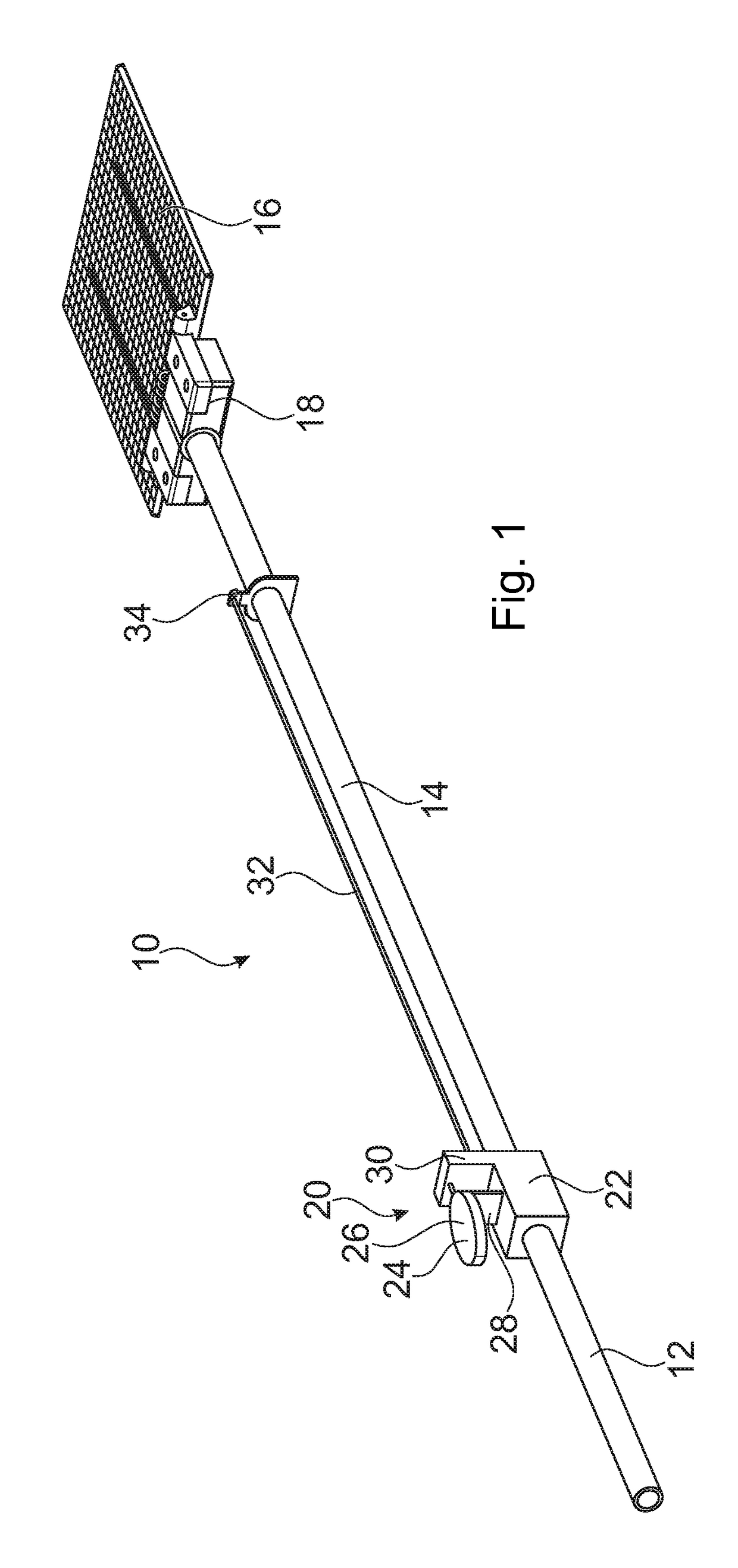
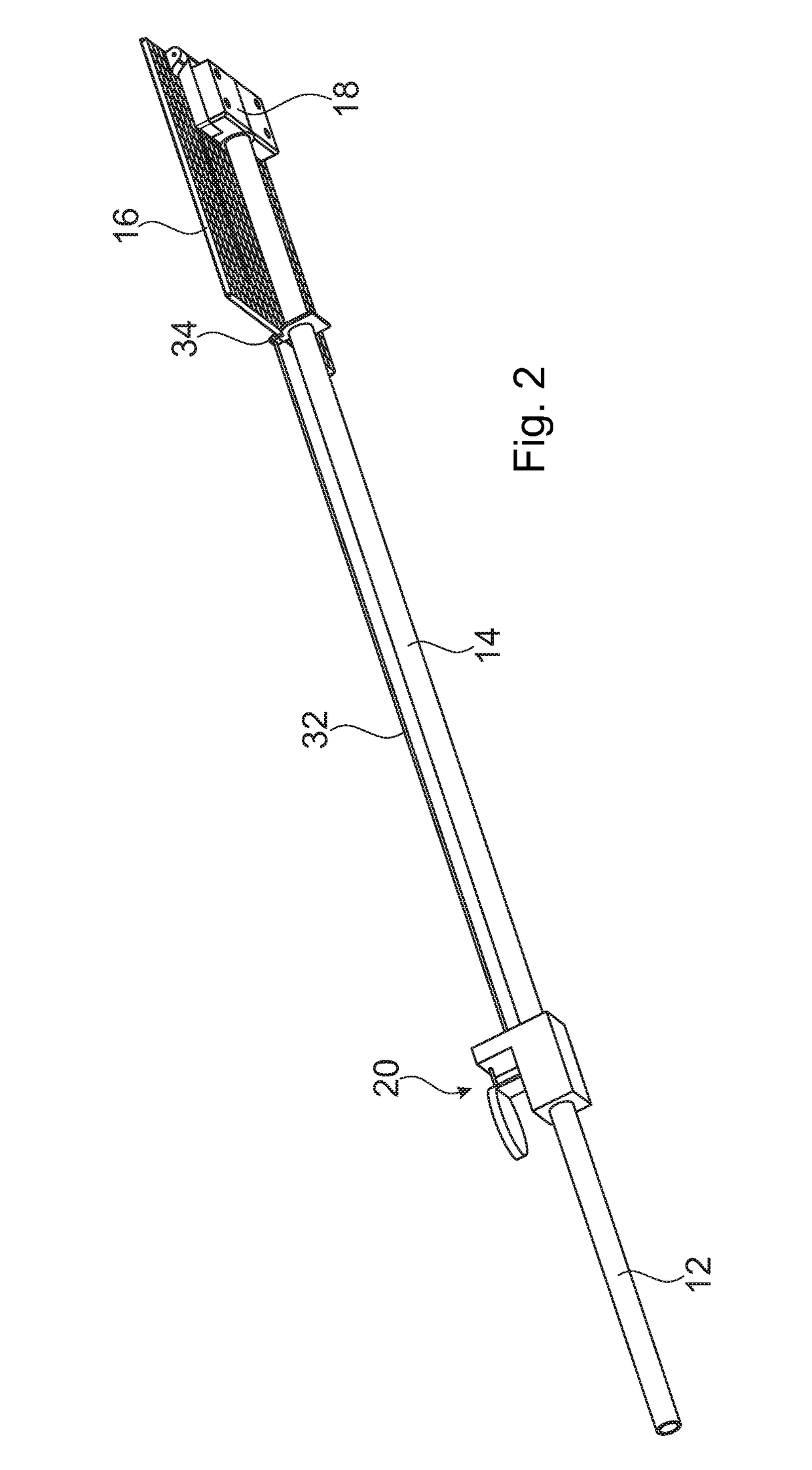
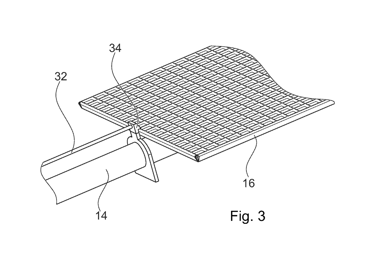
[0033]FIG. 1 shows a fly swatter generally designated with numeral 10. The fly swatter 10 comprises a handgrip 12, a stem 14 and a hitting grid 16. The handgrip 12 is aligned with the stem 14 and is essentially designed rod-shaped like the stem. The hitting grid 16 is joint to the stem 14 in the manner described below. The rotational axis of the joint 18 provided for this purpose extends in the plane of the hitting grid 16 perpendicularly to the longitudinal axis of the stem 14.

[0034]A trigger 20 is molded to the rod forming the handgrip 12 and the stem 14 between the handgrip and the stem 14. The trigger 20 comprises a broadened base 22. An angle 24 is attached to the base 22. The angle 24 provides a first leg 26 parallel to the longitudinal axis of the stem 14 which forms an imprint surface. A second leg 28 of the angle 24 extends perpendicularly thereto and connects the first leg 26 to the base 22.

[0035]The base 22 has an angular design and provides a projection 30 extending perp...


PUM


Abstract

A fly swatter (10) with a hitting grid (16) and a stem (14), whereby the hitting grid (16) is joint to the stem (14) by means of a joint; the hitting grid (16) is rotatable against the force of a spring (36) from a relaxed position about an axis which lies in the plane of the hitting grid (16) and runs perpendicularly to the longitudinal axis of the stem (14); the hitting grid (16) is lockable in a pre-loaded position with a locking device, and the locking mechanism of the locking device (34) is releasable by way of a trigger (20), is characterized in that the joint with the turning axis of the hitting grid is assembled between the stem and the hitting grid (16); the locking device (34) is assembled remote to the trigger (20); and a string, a wire or different means of transmission (32) are provided, which transfer a triggering force from the trigger (20) onto the locking device (34).

Description

CROSS REFERENCE TO RELATED PATENT APPLICATIONS[0001]To the fullest extent permitted by law, this nonprovisional utility patent application claims priority under 35 U.S.C. § 119 to Germany Patent Application No. 10 2017 121 734.7, with a filing date of Sep. 19, 2017.STATEMENT REGARDING FEDERALLY-SPONSORED RESEARCH OR DEVELOPMENT[0002]Not applicable.TECHNICAL FIELD[0003]The invention relates to a fly swatter with a hitting grid and a stem, wherein the hitting grid is hinged to the stem by means of a joint. The hitting grid is rotatable against the force of a spring from a relaxed position about an axis which lies in the plane of the hitting grid and runs perpendicularly to the longitudinal axis of the stem. The hitting grid is lockable in a pre-loaded position with a locking device, and the locking mechanism of the locking device is releasable by way of a trigger.[0004]Irritating flies, mosquitos, and other insects can be killed by means of a fly swatter. Simple fly swatters have a lo...

Claims


Application Information

Patent Timeline
Patent Type & Authority Applications(United States)
IPC IPC(8): A01M3/02
CPCA01M3/027A01M2200/012A01M3/02
Inventor LEBERER, THOMAS
Owner LEBERER THOMAS
Features
  • R&D
  • Intellectual Property
  • Life Sciences
  • Materials
  • Tech Scout
  • Unparalleled Data Quality
  • Higher Quality Content
  • 60% Fewer Hallucinations
Learn More