Video laryngoscope with monitor stabilization

a technology of laryngoscope and monitor, which is applied in the field of video laryngoscope, can solve the problems of monitor being at a less than ideal angle relative to the user, often out of the immediate field of view of the user, and losing patient situational awareness,

Active Publication Date: 2019-03-21
MONTANE MEDICAL CORP
View PDF16 Cites 11 Cited by
  • Summary
  • Abstract
  • Description
  • Claims
  • Application Information

AI Technical Summary

Benefits of technology

[0019]This invention uses a gimbal design to link the handle of any type of video laryngoscope to the monitor mounted directly on the handle. A gimbal is a device that permits a body to incline freely in any direction or suspends it so that it will remain level when it's support is tipped. In this way, the monitor module can be kept in a stable position relative to the horizon regardless of the position of the handle. Using a 3-axis gimbal set, with the outermost gimbal attached to the handle, and each successive gimbal mounted on the other with orthogonal pivot axes and the monitor mounted on the innermost gimbal will allow the monitor to remain independent of the rotation of it's support—the handle (see FIG. 2, 3).

Problems solved by technology

The disadvantages are that adjusting the monitor would require abandoning the attempt or a second person available to adjust the monitor and that the monitor is often out of the immediate field of view of the user.
Therefore, having the monitor out of the immediate line of site of the user may cause them to lose situational awareness of the patient during the attempt while the user glances between the monitor and the patient.
The disadvantage is that the once the procedure is started adjusting the monitor's position relative to the handle would require using the users right hand (which then can't be used for suction or holding the ET tube) or adjusting the user's head to allow a better view of the monitor.
As intubation is a dynamic process that requires the handle to move through a range of angles during the intubation attempt this means that at certain times during the attempt, the monitor will be at a less than ideal angle relative to the user (see FIG. 1).

Method used


Image

  • Video laryngoscope with monitor stabilization
  • Video laryngoscope with monitor stabilization
  • Video laryngoscope with monitor stabilization

Examples


Embodiment Construction

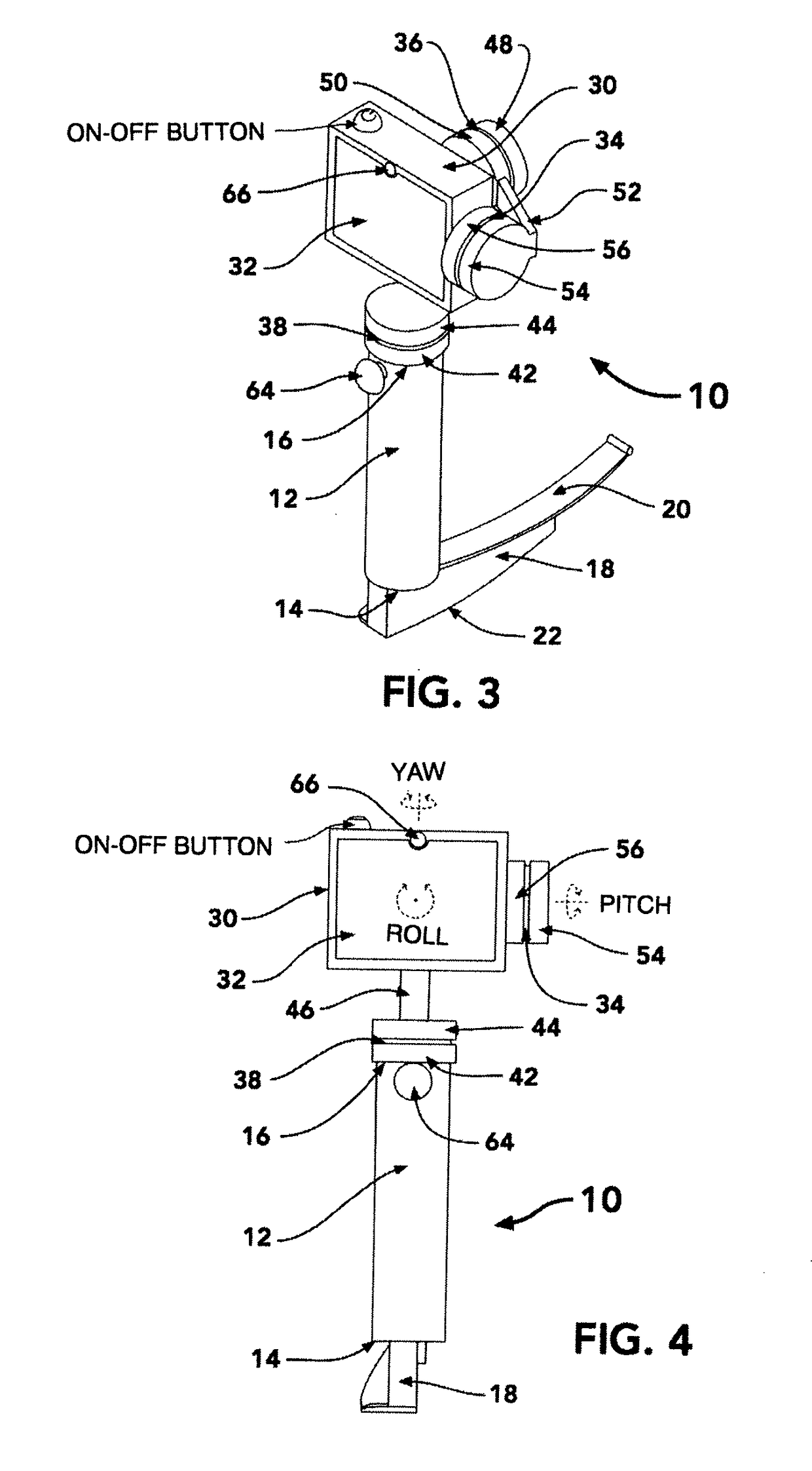
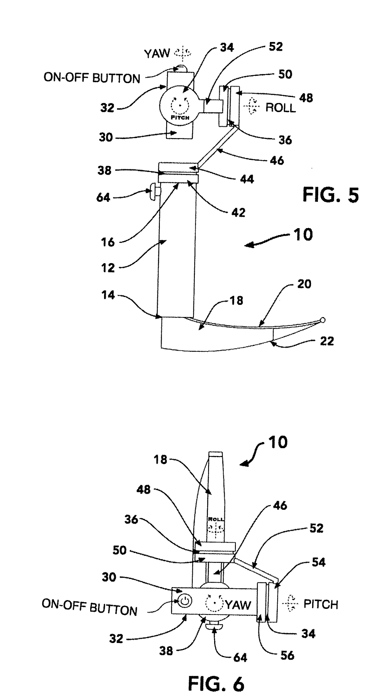
[0045]Referring to the accompanying figures there is illustrated a laryngoscope device generally indicated by reference numeral 10. The device 10 is particularly suited for use in laryngoscopy procedures. Laryngoscopy is endoscopy of the larynx, a part of the throat. It is a medical procedure that is used to obtain a view of the vocal folds and the glottis, for example, to facilitate tracheal intubation during anaesthesia or cardiopulmonary resuscitation or for surgical procedures on the larynx or other parts of the upper tracheobronchial tree.

[0046]Although various embodiments of the device are described and illustrated herein, the features in common with the various embodiments will first be described. The device 10 includes an elongate handle 12 which is elongate in a longitudinal direction between a first end 14 and an opposing second end 16. The handle is generally cylindrical in shape and sized so as to be suitably gripped within a single hand of an operator.

[0047]A laryngosco...


PUM


Abstract

A laryngoscope device with an elongate handle includes a video laryngoscope blade with a camera mounted transversely on a first end of the handle and one or more pivot assemblies coupling a display monitor on an opposing second end of the handle. Each pivot assembly includes a pivot coupling defining a respective axis of rotation of the display monitor relative to the handle and a motor for controlling angular position of the display monitor relative to the handle about the respective axis. A sensor device is arranged to detect movement of the display monitor away from a target orientation such that a controller having the target orientation stored thereon can be adapted to operate the motor to return the display monitor to the target orientation.

Description

[0001]This application claims the benefit under 35 U.S.C.119(e) of U.S. provisional application Ser. No. 62 / 504,755, filed May 11, 2017.FIELD OF THE INVENTION[0002]The present invention relates to a video laryngoscope device of the type which capturing and displaying a video image of the glottis of a patient to assist an operator in placing an endotracheal tube into the patient, and more particularly the present invention relates to a video laryngoscope device in which a display monitor for displaying the video images of the glottis to the operator is supported on a handle of the laryngoscope using at least one controlled pivot assembly which supports the display monitor in a target orientation regardless of the orientation of the handle.BACKGROUND[0003]A video laryngoscope is a relatively new development in the field of anaesthesia.[0004]Traditional DIRECT LARYNGOSCOPY (DL) involves using a blade with a light at the end to obtain a view of the glottis via a direct view from the max...

Claims


Application Information

Patent Timeline
Patent Type & Authority Applications(United States)
IPC IPC(8): A61B1/00A61B1/267A61B1/045
CPCA61B1/00048A61B1/267A61B1/045A61B1/00039A61B1/00016A61B1/00052A61B1/00042
Inventor SCHOONBAERT, IAN
Owner MONTANE MEDICAL CORP
Why Eureka
Try Eureka