Safety gate

Active Publication Date: 2019-03-21
DEMBY DEV
View PDF0 Cites 6 Cited by
  • Summary
  • Abstract
  • Description
  • Claims
  • Application Information

AI Technical Summary

Benefits of technology

[0006]The main objective of the present invention is to provid

Problems solved by technology

However, it is complicated to install and disassemble the conventional safety gate fr

Method used


Image

  • Safety gate
  • Safety gate
  • Safety gate

Examples


Embodiment Construction

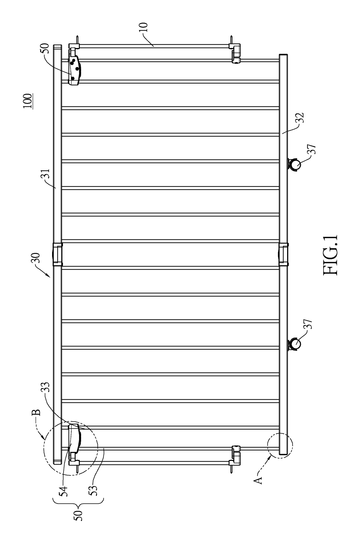
[0026]With reference to FIG. 1, a safety gate 100 in accordance with the present invention comprises a main frame 30, two wall-mounted assemblies 10, and two connecting assemblies 50. The two connecting assemblies 50 are respectively mounted on two opposite sides of the main frame 30. Each connecting assembly 50 is movably mounted on the main frame 30. The two wall-mounted assemblies 10 correspond in position to the two connecting assemblies 50. The connecting assemblies 50 have a pivoting condition and a disassembling condition. In the pivoting condition, the user operates one of the two connecting assemblies 50, so the main frame 30 may be unlocked and detached from one of the wall-mounted assemblies 10, being rotatable against the other wall-mounted assembly 10. Therefore, the main frame 30 may be opened or closed on either side, so the safety gate 100 is convenient to use.

[0027]On the other hand, in the disassembling condition, by operating both of the connecting assemblies 50, ...


PUM


Abstract

A safety gate has a main frame, two wall-mounted assemblies, and two connecting assemblies. The two connecting assemblies are respectively and movably mounted on two opposite sides of the main frame. Each connecting assembly has a first connecting part and a second connecting part. Each wall-mounted assembly has a first pivot base and a second pivot base. Each first connecting part is rotatably and detachably connected to a corresponding first pivot base. Each second connecting part is rotatably and detachably connected to a corresponding second pivot base. By detaching and rotating one connecting assembly from the corresponding wall-mounted assembly, the main frame can be closed and opened as a gate. By detaching all the connecting parts from the corresponding bases, the main frame can be easily installed on and disassembled from a place.

Description

CROSS-REFERENCE TO RELATED APPLICATIONS[0001]This application is based upon and claims priority under 35 U.S.C. 119 from China Patent Application No. 201721190203.7 filed on Sep. 15, 2017, which is hereby specifically incorporated herein by this reference thereto.BACKGROUND OF THE INVENTION1. Field of the Invention[0002]The present invention relates to a gate, especially to a safety gate.2. Description of the Prior Arts[0003]A conventional safety gate has a main frame, a rotating shift, and a door lock. The rotating shift and the door lock are mounted on two opposite sides of the main frame. The rotating shift is mounted on a wall. The door lock is selectively mounted on another wall, and can make the main frame locked or unlocked against the wall.[0004]However, it is complicated to install and disassemble the conventional safety gate from one place to another place, so the conventional safety gate is inconvenient to use.[0005]To overcome the shortcomings, the present invention prov...

Claims


Application Information

Patent Timeline
IPC IPC(8): E06B9/06E05B65/00
CPCE06B9/0638E05B65/0007E06B2009/002E06B9/02
Inventor WANG, TSUNG-HSIANG
Owner DEMBY DEV
Why Eureka
Try Eureka