
Oblique viewing endoscope and imaging system

Active Publication Date: 2019-03-21
PANASONIC I PRO SENSING SOLUTIONS CO LTD
View PDF3 Cites 1 Cited by
  • Summary
  • Abstract
  • Description
  • Claims
  • Application Information

AI Technical Summary

Benefits of technology

The patent is about a new type of camera that can be used in endoscopes. The new camera can be small and capture images in a way that allows the endoscope to look forward and at an angle. This means that the camera can be made smaller and the number of components used in the endoscope can be minimized.

Problems solved by technology

Therefore, the oblique viewing endoscope in the related art needs a large number of components, thereby causing a problem in that a structure for a distal end portion is less likely to be miniaturized.
Consequently, there is a problem in that a maximum outer diameter of the endoscope becomes large.
In order to avoid this problem, if an image side is set to an optical system close to a telecentric system, a lens system becomes large, thereby causing a problem in that an outer diameter of the endoscope becomes large.

Method used


Image

  • Oblique viewing endoscope and imaging system
  • Oblique viewing endoscope and imaging system
  • Oblique viewing endoscope and imaging system

Examples


exemplary embodiment 1

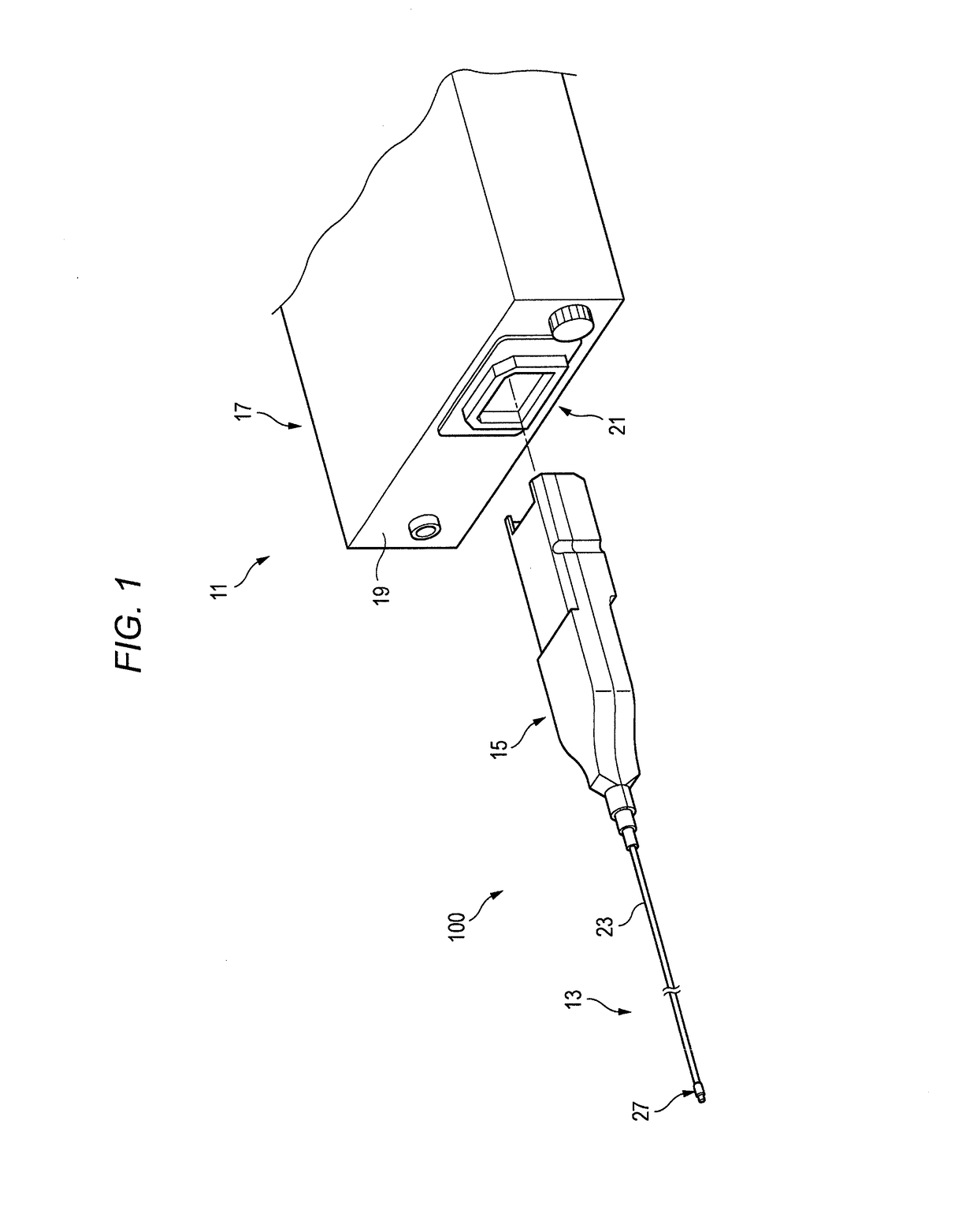
[0060]FIG. 1 is an overall configuration diagram illustrating an example of oblique viewing endoscope system 11 using oblique viewing endoscope 100 according to Exemplary Embodiment 1.

[0061]For example, oblique viewing endoscope system 11 is configured to include elongated oblique viewing endoscope 100 which is a flexible mirror for medical uses, and a console (not illustrated) which performs known image processing on a still image or a moving image obtained by imaging an interior of an observation target (for example, a blood vessel of a human body). Oblique viewing endoscope 100 includes insertion portion 13 located on one end side (front side) in a longitudinal direction which is inserted into the observation target, and a plug 15 to which a rear portion of insertion portion 13 is connected.

[0062]A cable (not illustrated) is connected to the console. Repeater 17 is attached to a distal end of the cable. Repeater 17 has a socket portion 21 disposed on front surface panel 19. A rea...

exemplary embodiment 2

[0137]Next, exemplary embodiment 2 will be described. In Exemplary Embodiment 2, the same reference numerals will be given to members the same as the members described in Exemplary Embodiment 1, and repeated description will be omitted.

[0138]FIG. 13 is a perspective view when distal end portion 27 of oblique viewing endoscope 200 according to Exemplary Embodiment 2 is viewed from the front side.

[0139]In oblique viewing endoscope 200 according to Exemplary Embodiment 2, imaging element 29 is located in a tilting manner. In imaging element 29, light receiving center 57 perpendicular to light receiving plane 51 is located tilting in the visual field direction with respect to axial line 43 of columnar distal end portion 27 for accommodating lens 35 and imaging element 29. As imaging element 29, the same one as that according to Exemplary Embodiment 1 can be used in the tilting manner. Therefore, as oblique viewing endoscope 200, it is possible to use a member the same as that of oblique...

exemplary embodiment 3

[0172]Next, Exemplary Embodiment 3 will be described. In Exemplary Embodiment 3, the same reference numerals will be given to members the same as the members described in Exemplary Embodiment 1, and repeated description will be omitted.

[0173]FIG. 22 is a perspective view when distal end portion 27 of oblique viewing endoscope 300 according to Exemplary Embodiment 3 is viewed from the front side.

[0174]FIG. 23 is a plan view of the sheath interior of oblique viewing endoscope 300 according to Exemplary Embodiment 3.

[0175]In oblique viewing endoscope 300, front stage lens 67 is disposed between objective cover glass 31 and lens 35. In oblique viewing endoscope 300, a distance from objective cover glass 31 to lens 35 is longer than that of oblique viewing endoscope 100, as front stage lens 67 is disposed between objective cover glass 31 and lens 35.

[0176]FIG. 24 is a side view of the sheath interior of oblique viewing endoscope 300 according to Exemplary Embodiment 3.

[0177]FIG. 25 is a ...


PUM


Abstract

An oblique viewing endoscope has an aperture through which some rays out of rays reflected from an object in an oblique viewing direction pass, an imaging element that captures an image, based on image forming of the rays passing through the aperture, and a lens that is disposed between the aperture and the imaging element, and that has a lens surface on which the image is formed by causing some rays in at least a visual field center out of the rays passing through the aperture in the oblique viewing direction to be substantially vertically incident on a center of the imaging element.

Description

BACKGROUND1. Technical Field[0001]The present disclosure relates to an oblique viewing endoscope and an imaging system which have a forward oblique viewing optical system.2. Description of the Related Art[0002]In the related art, as an imaging device, a lateral viewing-type medical endoscope (hereinafter, referred to as an “oblique viewing endoscope”) is known which can observe a body cavity of a human body or an inner wall surface of a tube. For example, Japanese Patent Unexamined Publication No. 2010-97208 (PTL 1) discloses an oblique viewing endoscope including a forward oblique viewing optical system.[0003]FIG. 43 is a layout view of the forward oblique viewing optical system in the related art. As illustrated in FIG. 43, in the oblique viewing endoscope, objective system 2A2 which is the forward oblique viewing optical system has prism PA2 for a forward oblique viewing angle of 45°. Front lens group G1 having positive refractive power is located between an object and prism PA2....

Claims


Application Information

Patent Timeline
IPC IPC(8): G02B23/24H04N5/225H04N9/04A61B1/00A61B1/05A61B1/07
CPCG02B23/243G02B23/2484H04N5/2254H04N9/04517A61B1/00179A61B1/05A61B1/00009A61B1/07A61B1/00195H04N2005/2255A61B1/00163A61B1/04H04N23/80A61B1/00096A61B1/051G02B23/2423G02B3/02G02B5/04H04N23/555H04N23/55H04N25/611
Inventor SUEYOSHI, MASAFUMIHATASE, YUICHI
Owner PANASONIC I PRO SENSING SOLUTIONS CO LTD
Features
  • Generate Ideas
  • Intellectual Property
  • Life Sciences
  • Materials
  • Tech Scout
  • Unparalleled Data Quality
  • Higher Quality Content
  • 60% Fewer Hallucinations
Learn More