
Flexible surgical screw driver

a screw driver and flexible technology, applied in the field of flexible surgical screw drivers, can solve the problems of obstructing the view of surgeons, insufficient constrained universal joints, and swiveling of the screw driver drive tip

Active Publication Date: 2019-03-28
SWEMAC INNOVATION
View PDF7 Cites 5 Cited by
  • Summary
  • Abstract
  • Description
  • Claims
  • Application Information

AI Technical Summary

Benefits of technology

The present invention aims to improve a flexible surgical screw driver by allowing for easy angular displacement of the handle and shaft members for reaching and engaging difficult targets, while safely and effectively transmitting torque without any loss. Furthermore, after use, the screw driver automatically reverses its angular displacement, allowing for easy and accurate placement of the screw. This invention provides a more efficient and flexible tool for surgical procedures.

Problems solved by technology

First, it is very bulky.
It needs much space, it is too big for easy positioning of the screw driver in correct location for use and it obstructs the view for the surgeon.
Secondly, the universal joint is not sufficiently constrained.
In fact, it is fully non-constrained, resulting in that the drive tip of the screw driver is swiveling free in all directions and cannot be directed or controlled to get to a specific target such as a screw.
On the other hand, the coil is for natural reasons configured such that it opens and closes, allowing body fluids to enter the coil and the coil is difficult, if not impossible, to clean.
The result is that the prior art cannot provide a flexible surgical screw driver wherein these two functions are combined in a satisfactory manner.

Method used


Image

  • Flexible surgical screw driver
  • Flexible surgical screw driver
  • Flexible surgical screw driver

Examples


Embodiment Construction

[0015]The present invention will in the following be exemplified by embodiments. It should however be realized that the embodiments are included to explain principles of the invention and not to limit the scope of the invention as defined in the appended claims. Details from the embodiments may be combined with each other.

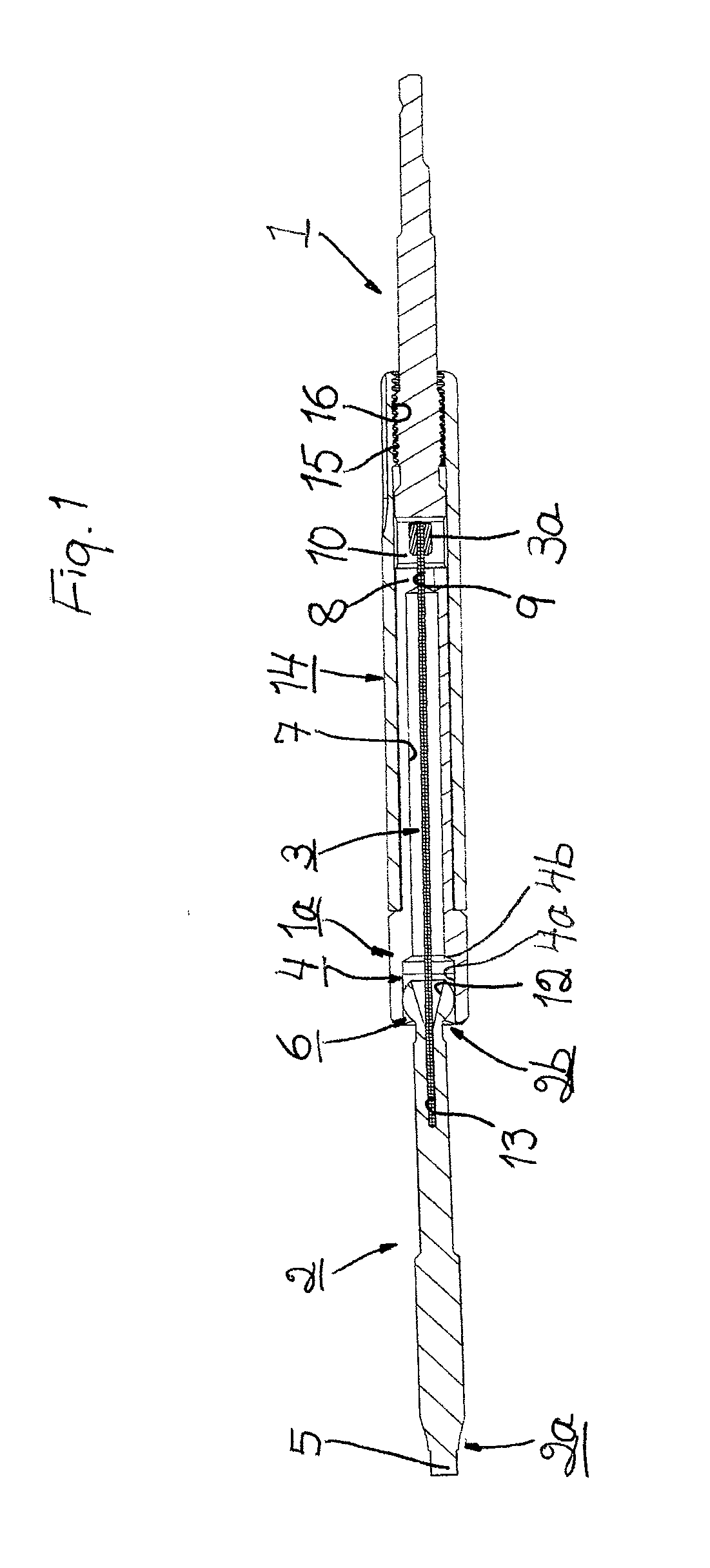
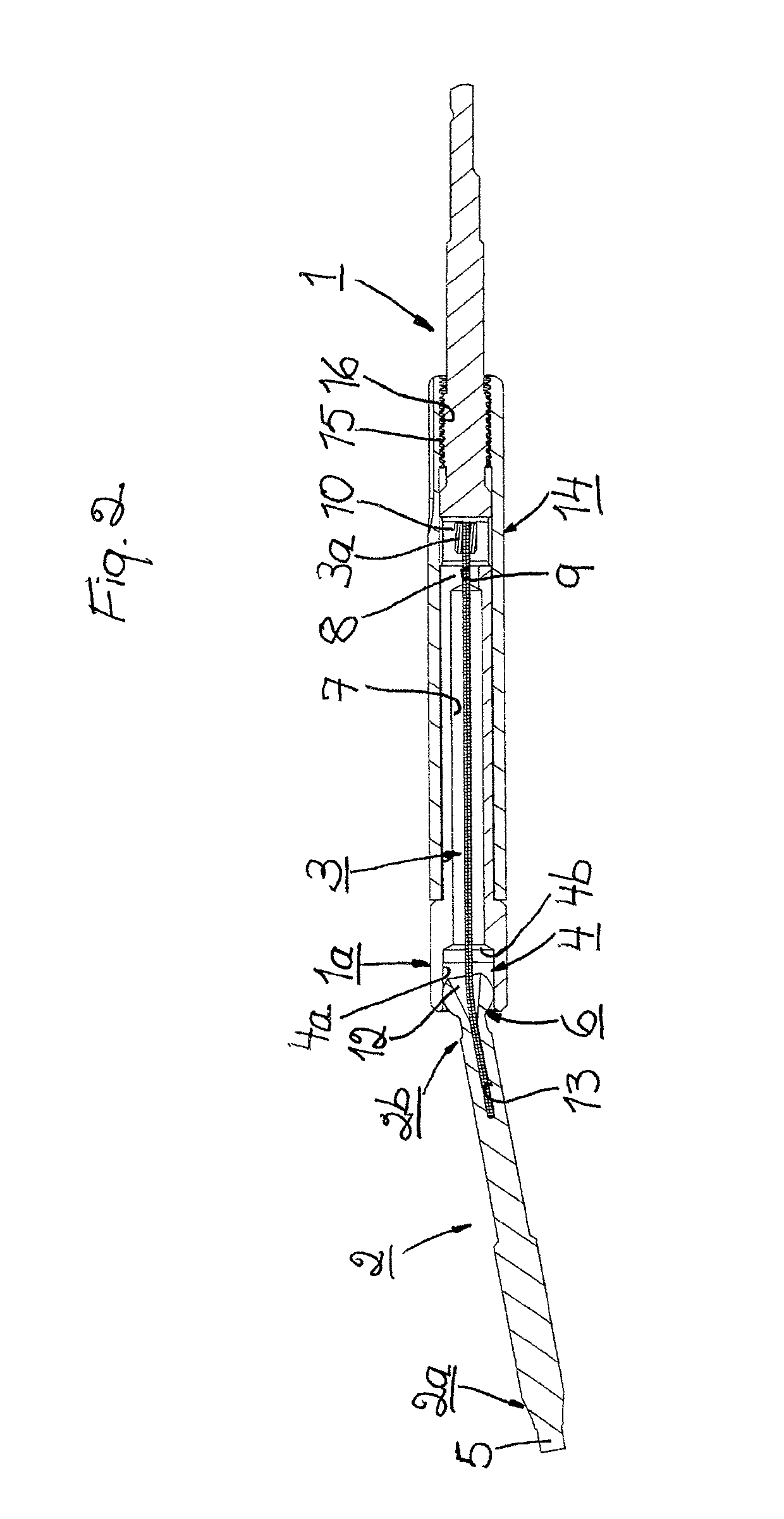
[0016]FIGS. 1 and 2 illustrate as mentioned a preferred first embodiment of the flexible surgical screw driver according to the present invention. This flexible surgical screw driver comprises a rotatable handle member 1, a shaft member 2 and a flexible member 3.

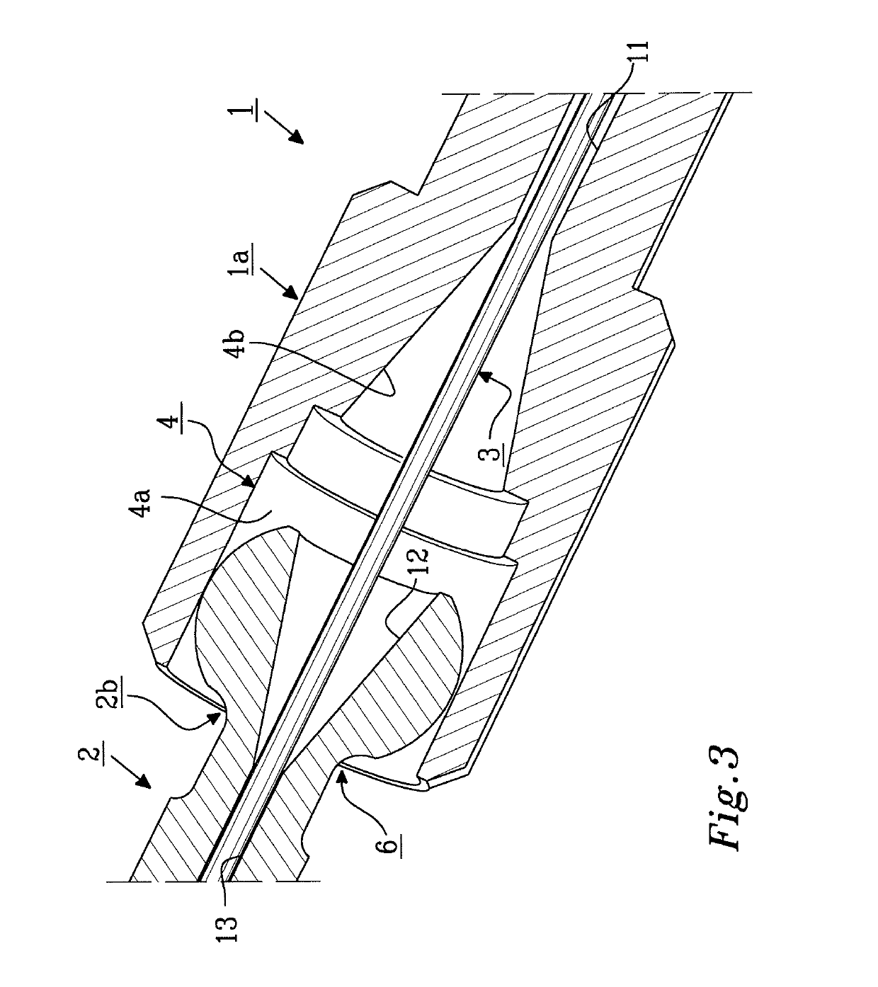
[0017]The rotatable handle member 1 is configured with a first coupling means 4. This first coupling means 4 is located on a distal end portion 1a of the handle member 1. The shaft member 2 is configured with a drive tip 5. The drive tip is located on a distal end portion 2a of the shaft member 2. The shaft member 2 is also configured with a second coupling means 6. This second coupling means 6 is found on ...


PUM


Abstract

A flexible surgical screw driver comprises a rotatable handle member, a shaft member and a flexible member. The handle member is configured with a first coupling means and the shaft member with a second coupling means. These first and second coupling means are configured to cooperate such that the handle member and the shaft member are angularly displaceable relative to each other and such that said handle member and said shaft member are non-rotatably coupled to each other for driving a screw with rotation transmitted from the handle member. The flexible member is configured to connect the handle member and the shaft member to each other and hold said handle member and said shaft member together such that the longitudinal axes thereof are substantially aligned and such that angular displacement of the handle member and the shaft member relative to each other such that the longitudinal axes thereof are misaligned, can be performed against the action of said flexible member.

Description

TECHNICAL FIELD[0001]The present invention relates to a flexible surgical screw driver. The screw driver comprises a rotatable handle member, a shaft member and a flexible member. The handle member is configured with a first coupling means on a distal portion thereof. The shaft member is configured with a drive tip on a distal portion thereof and with a second coupling means on a proximal portion thereof. The first and second coupling means are configured to co-operate for permitting angular displacement of the handle member and the shaft member relative to each other and for transmitting torque from the handle member to the shaft member.BACKGROUND OF THE INVENTION[0002]Flexible surgical screw drivers are already known in the prior art.[0003]Thus, one type of prior art flexible screw driver uses a universal joint as coupling means to achieve angular displacement or angulation of the shaft member relative to the handle member and for transmitting torque from the handle member to the ...

Claims


Application Information

Patent Timeline
IPC IPC(8): A61B17/88A61B17/16
CPCA61B17/8875A61B17/1631A61B17/808B25B15/00B25B23/0042
Inventor LUTZ, CHRISTIANDORAWA, KLAUS
Owner SWEMAC INNOVATION
Learn More