
Machine element

a machine element and element technology, applied in the field of machine elements, can solve the problems of mutual contamination already occurring, damage already occurring, contamination of each other, etc., and achieve the effect of quick and easy finding ou

Active Publication Date: 2019-03-28
ENGEL AUSTRIA
View PDF0 Cites 0 Cited by
  • Summary
  • Abstract
  • Description
  • Claims
  • Application Information

AI Technical Summary

Benefits of technology

The invention provides a way to collect a certain amount of a medium (e.g. gas or liquid) using a device. This helps to accurately measure the amount of fluid. The method is particularly useful when the medium is pressure-less, as direct volume flow measurement is not always accurate. The patent also suggests using multiple collecting devices to quickly and easily find out where a leak is occurring.

Problems solved by technology

By virtue thereof the operator of the installation can be warned if damage to the rotary feedthrough occurs, and as a result larger amounts of lubricant or media issue and possibly contaminate each other.
If however the pressure in the drainage conduit is already increased the risk of mutual contamination naturally already arises, that is to say in general damage has already occurred.

Method used


Image

  • Machine element
  • Machine element

Examples


Embodiment Construction

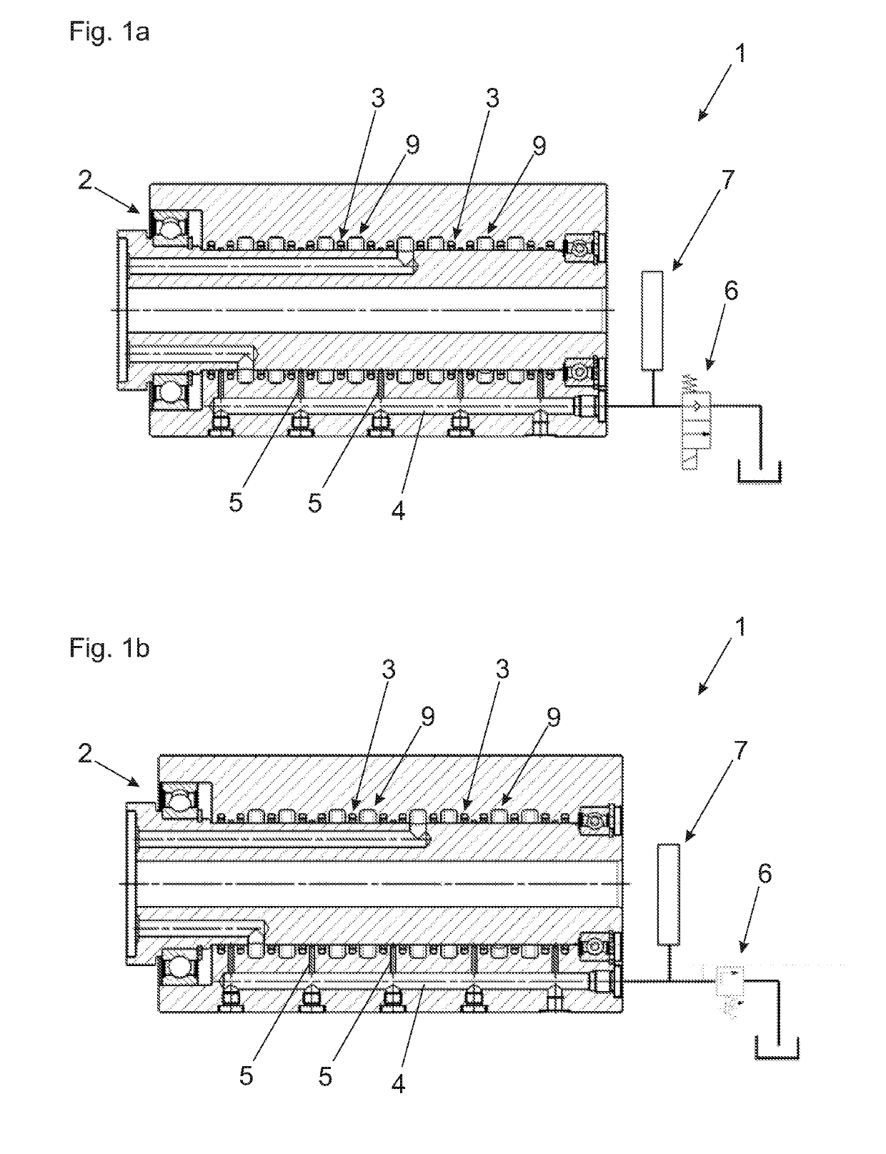
[0037]The machine element 1 shown in FIG. 1a is a rotary feedthrough or union. It has a plurality of media passages 9 which are sealed off relative to each other by seals 3.

[0038]There are also a plurality of separate drainage conduits 5 which all open into a main drainage conduit 4.

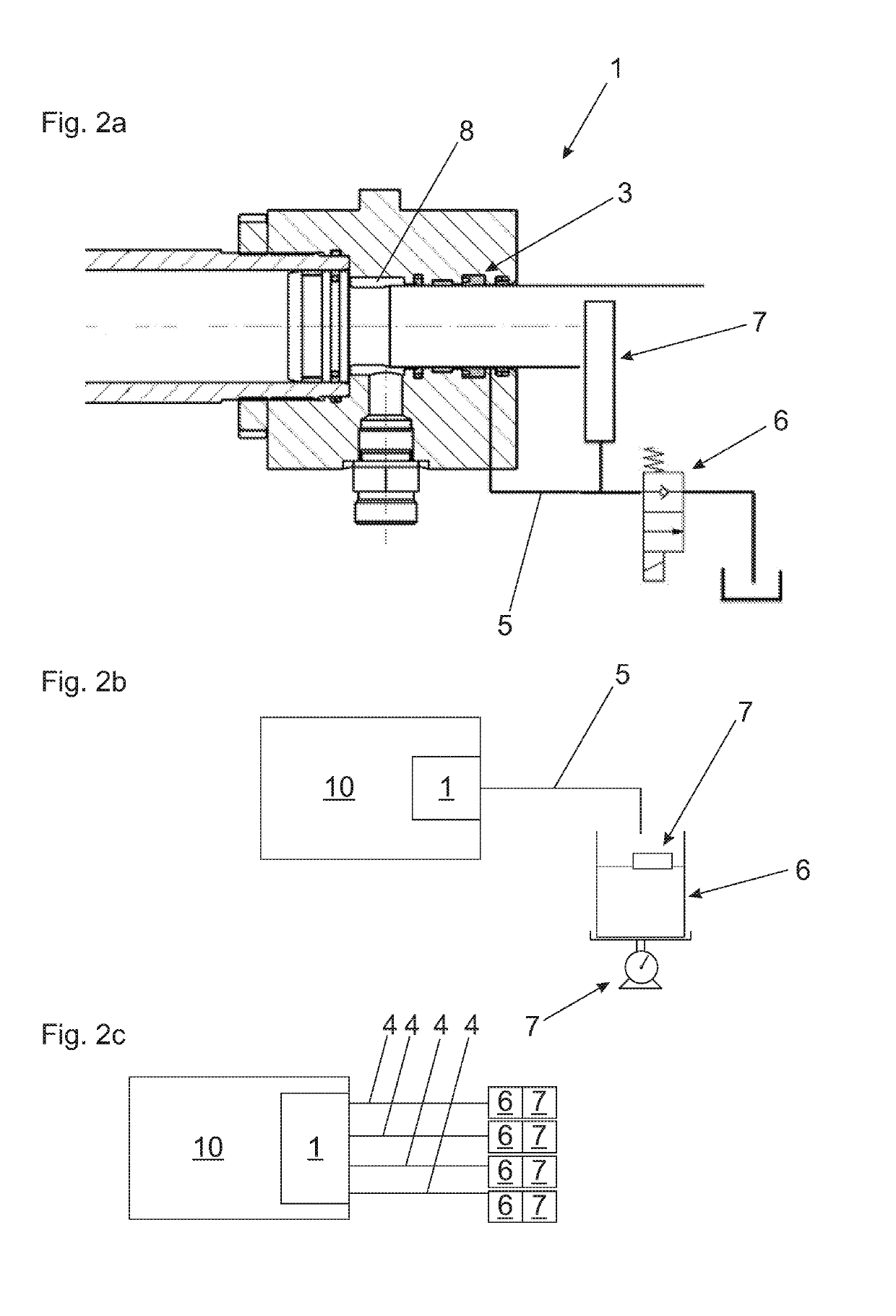
[0039]In that respect it is to be mentioned that the main drainage conduit 4 can be composed of a main drainage passage in a component of the rotary feedthrough and a flexible or non-flexible conduit portion connected thereto, like for example a tube or a hose. In the present embodiment a stop valve which for example is in the form of a two-way valve serves as the collecting device 6. A corresponding stop valve can be actuated electrically or electronically, in which respect theoretically it is also possible to use a hand-operated stop valve. In addition there is a measuring device in the form of a pressure sensor.

[0040]The stop valve can be opened at regular intervals and thereafter it is possible by me...


PUM

PropertyMeasurementUnit
pressureaaaaaaaaaa
timeaaaaaaaaaa
pressureaaaaaaaaaa

Abstract

A machine element, in particular for a shaping machine, having a lubricated bearing and / or a seal and at least one drainage conduit for catching a medium issuing from the bearing and / or the seal, preferably substantially pressure-lessly. A collecting device is provided for collecting the medium which is caught in the at least one drainage conduit over a period of time, and a measuring device is adapted to directly and / or indirectly measure an amount of the medium collected by the collecting device over the period of time.

Description

BACKGROUND OF THE INVENTION[0001]The present invention concerns a machine element, in particular for a shaping machine, having a lubricated bearing and / or a seal and at least one drainage conduit for catching a medium issuing from the bearing and / or the seal, preferably substantially pressure-lessly, in accordance with the features of the classifying portion of claim 1, and a corresponding method.[0002]The state of the art is illustrated hereinafter by reference to the example of a rotary feedthrough.[0003]Rotary feedthroughs as are used in particular in shaping machines like for example injection moulding machines make it possible for media circulations, in particular of fluid, that is to say gaseous or liquid media, to be transmitted from a component to a shaft which rotates in relation to the component.[0004]The media passages of those rotary feedthroughs are provided with annular seals on the one hand to prevent the media from issuing from the media passage and on the other hand...

Claims


Application Information

Patent Timeline
Patent Type & Authority Applications(United States)
IPC IPC(8): B23Q11/12F16C33/66
CPCB23Q11/123F16C33/6625F16N29/02B29C45/83F16N31/00F16N2270/20F16C33/6659F16C33/6677F16C33/78F16N7/38F16N2210/14B29C45/76B29C45/18B29C2945/76056B29C2945/76331
Inventor KAPPELMUELLER, WERNERPOECHEIM, MARTINBAUER, JOHANNES
Owner ENGEL AUSTRIA
Learn More