Method and device for determining the heat loss coefficient of a premises

Active Publication Date: 2016-09-20
SAINT-GOBAIN GLASS FRANCE
View PDF3 Cites 0 Cited by
  • Summary
  • Abstract
  • Description
  • Claims
  • Application Information

AI Technical Summary

Benefits of technology

[0007]It is these drawbacks that the invention is intended more particularly to remedy by proposing a method and a device makin

Problems solved by technology

Such softwares are relatively tricky to implement and have the drawback of providing only a theoretical result, which does not assess such real parameters as the effective implementation o

Method used


Image

  • Method and device for determining the heat loss coefficient of a premises
  • Method and device for determining the heat loss coefficient of a premises
  • Method and device for determining the heat loss coefficient of a premises

Examples


Example

Example 1

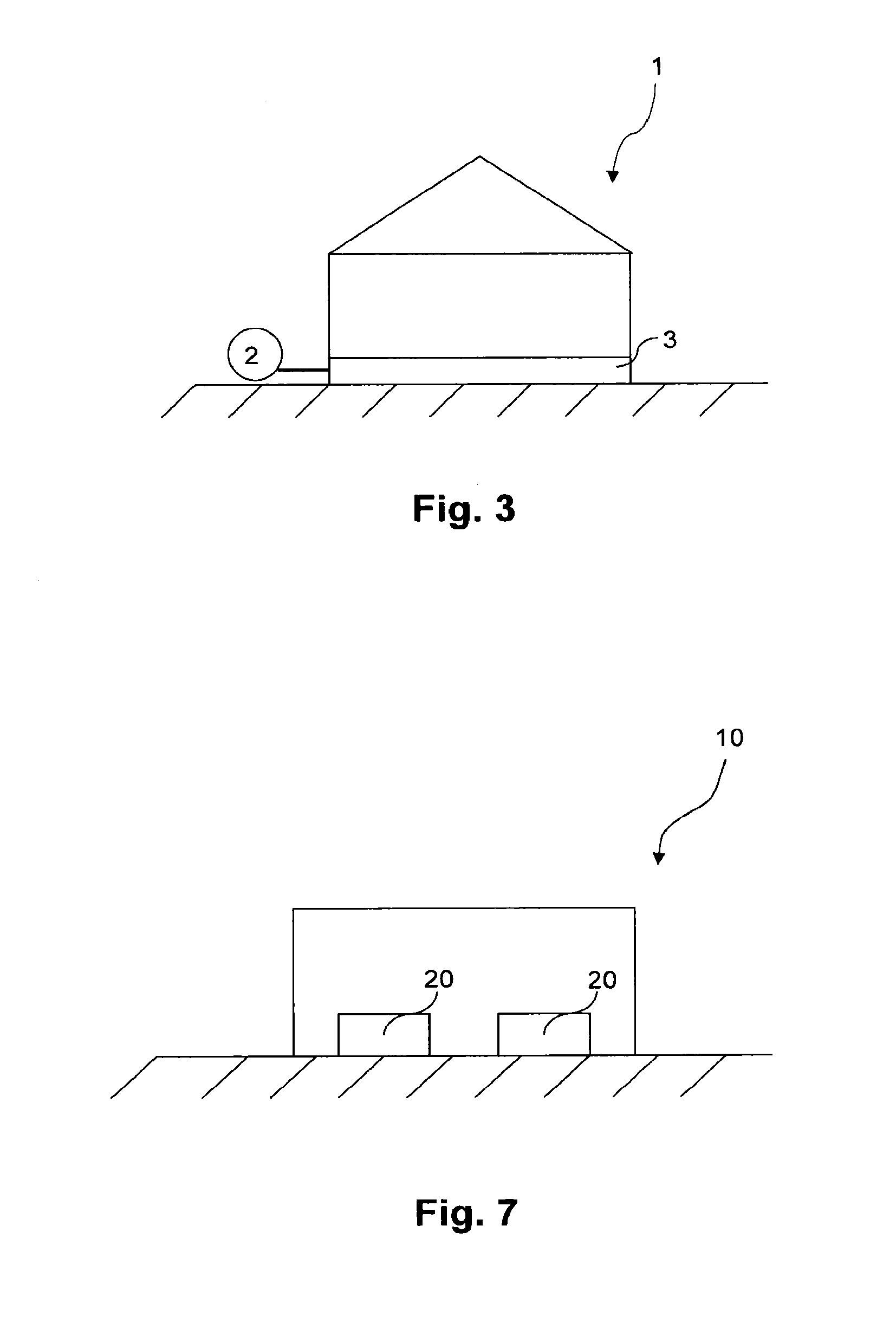
[0117]With reference to FIG. 3, the method according to the invention is implemented for the determination of the heat loss coefficient K of an individual house 1 of recent construction, equipped with a heat pump 2. The heat pump 2 feeds a floor-based heating system 3 allowing homogeneous heating of the house. In particular, the floor-based heating system 3 ensures heating of the house 1 such that the temperature of the walls inside the house is substantially equal to the temperature of the ambient air inside the house. The heat loss coefficient K of the house 1 may be sought within the framework of a diagnosis of the energy performance of the house, for example to verify that the house 1 satisfies certain quality labels in terms of thermal insulation, such as the BBC label or the Passivhaus label.

[0118]The heating power provided by the heat pump 2 for the heating of the house is readily determinable, in particular on the basis of the COP of the heat pump as explained previ...

Example

Example 2

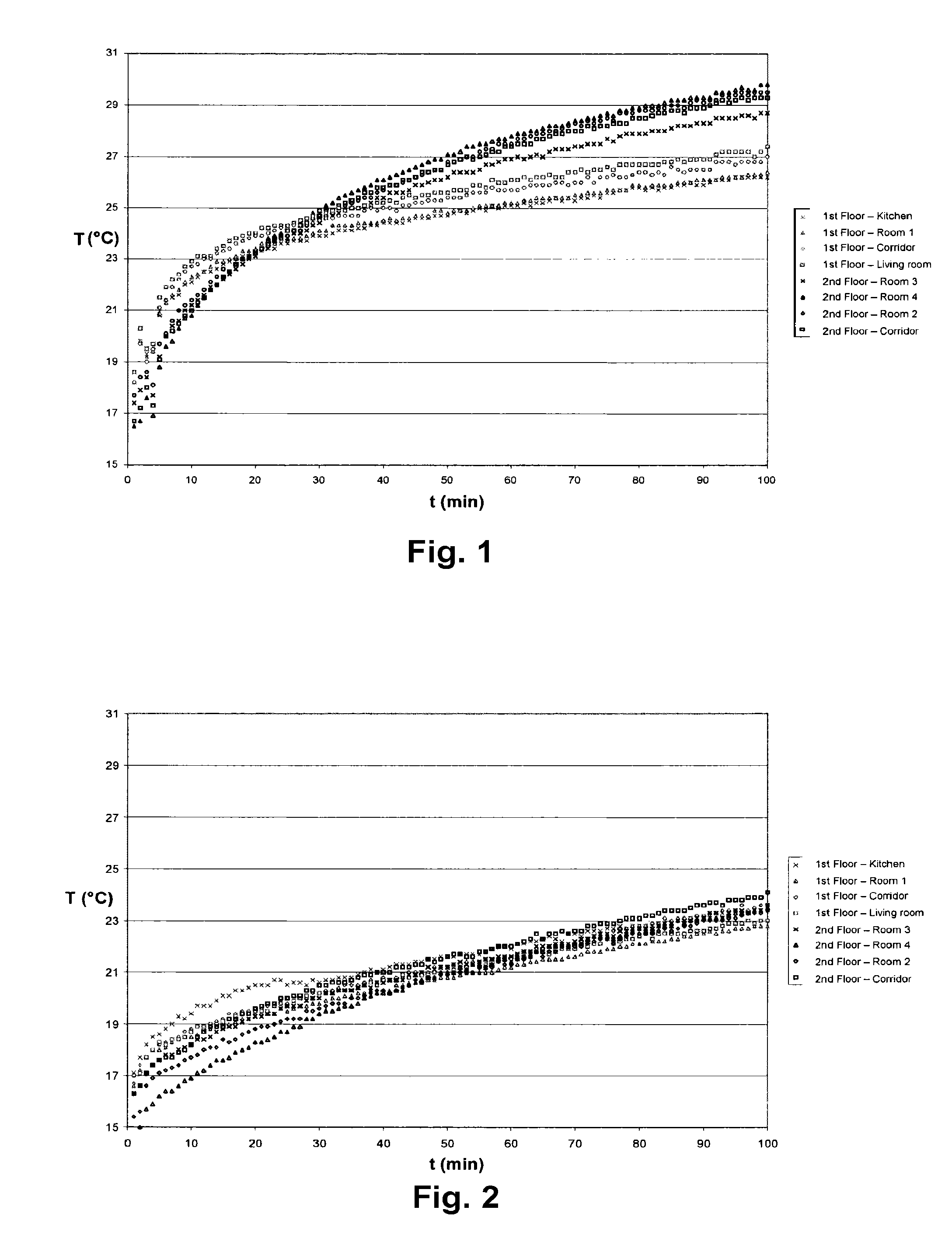
[0144]With reference to FIGS. 7 and 8, the method according to the invention is implemented for the determination of the heat loss coefficient K of a bungalow 10 which has an interior volume Vi of 5.8 m×2.1 m×2.6 m and which is fitted with two triple-glazed windows. The envelope of the bungalow 10 consists of insulating sandwich panels assembled via a metallic structure. An additional insulation has been added to the envelope, in the form of a 40 mm thickness of glass wool and of a plasterboard as interior lining of the envelope. The permeability to air, measured by tracer gas, is 0.43 vol / h. The method is implemented whilst the bungalow is unoccupied.

[0145]The heating of the bungalow 10 is ensured by electric convectors 20 having a measured actual power of 1880 W. The convectors make it possible to heat the air in the bungalow and, on account of the limited volume of the bungalow, the heating of the bungalow is homogeneous. The convectors 20 constitute a controlled power s...

Example

Example 3

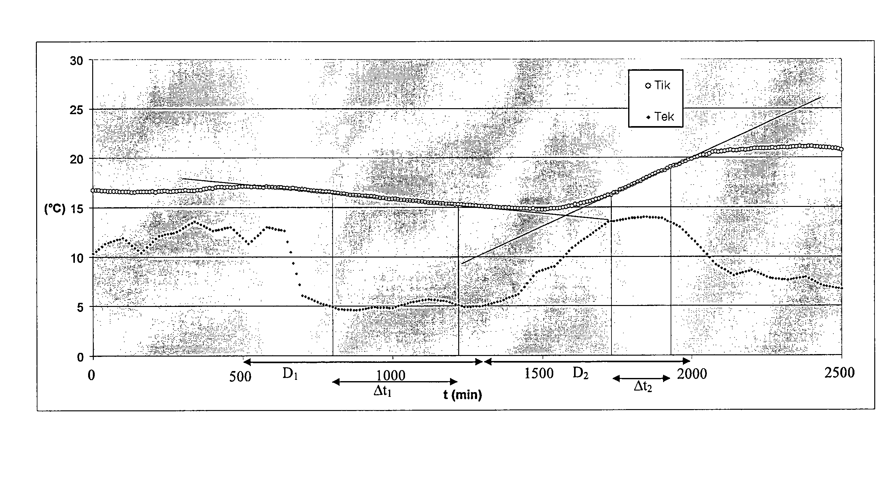
[0172]In order to verify the validity of the assumptions upon which the method of the invention rests, virtual trials have been carried out with the TRNSYS software on a fictitious house having an inhabited part of 12.10 m×9.90 m×2.50 m and a total loss area S=350 m2. More precisely, two series of computations have been performed:[0173]a first series corresponding to steady conditions obtained with a non-realistic weather file, with no sun and by fixing the outside temperature at 10° C. and the power at 30 kW during the time required for the temperatures to stabilize (400 hours at the maximum);[0174]a second series corresponding to transient conditions obtained with a realistic weather file, namely 3 days in March for a climate matched to the town of Chambéry, by supplying power distributed homogeneously, either via the floor at the surface (not depth-wise), or via the air, of 30 kW from 7 pm to midnight, and of 3 kW during the following 36 hours, after regulation to 19° C....


PUM


Abstract

A method determining heat loss coefficient K of a premises, includes: in unoccupied premises, performing a campaign of measurements of at least one temperature inside the premises Tik at closely-spaced time intervals over at least two successive time periods Dk corresponding to distinct heating powers Ptotk of the premises; determining temperature of outside air Tek at the same closely-spaced times; for each time period Dk, on the basis of evolution Tik(t) of a quantity Tik as a function of time, selecting a time interval Δtk for which the evolution Tik(t) is substantially linear, then determining the slope αk of the tangent to the evolution Tik(t) over this time interval Δtk, and deducing the value of the heat loss coefficient K of the premises on the basis of the slopes αk.

Description

BACKGROUND[0001]The present invention relates to a method and a device for determining the heat loss coefficient of a premises. Within the meaning of the invention, a premises is an individual house or a building, in particular for residential or tertiary use, or else a part of such a building, for example an apartment in a building with multiple floors.[0002]The heat loss coefficient of a premises, denoted K, is equal to the heat loss power of the premises (in Watts) per degree (Kelvin or Celsius) of difference between the temperature of the air inside the premises and the temperature of the outside air. This coefficient K is representative of the energy performance of the envelope of the premises.[0003]The heat loss coefficient K of a premises is influenced, on the one hand, by the heat losses by transmission through the walls of the premises and, on the other hand, by infiltrations of air. The heat losses by transmission are represented by a factor HT=UAT, where U is the heat tra...

Claims


Application Information

Patent Timeline
IPC IPC(8): G06F11/00G01N25/00G01K17/20
CPCG01N25/00G01K17/20
Inventor MANGEMATIN, ERICPANDRAUD, GUILLAUMEGILLES, JEROMEROUX, DIDIER
Owner SAINT-GOBAIN GLASS FRANCE
Why Eureka
Try Eureka