Eureka AIR delivers breakthrough ideas for toughest innovation challenges, trusted by R&D personnel around the world.

Axial fan

Active Publication Date: 2019-03-28
NIDEC CORP
View PDF0 Cites 1 Cited by
  • Summary
  • Abstract
  • Description
  • Claims
  • Application Information

AI Technical Summary

Benefits of technology

This patent is about a fan motor that can rotate at high speeds and is designed to maintain stability and secure fixing of the impeller and rotor yoke, even when exposed to high temperatures. The fan motor includes a hub with blades and a joining portion that joins a wall portion to the hub tubular portion. The rotor portion includes a rotor tubular portion that is in contact with at least one of the wall portions. The technical effect of this patent is to provide a fan motor that can operate stably and efficiently under high temperatures while preventing deformation of the impeller blade portion and maintaining secure fixing of the impeller and rotor yoke.

Problems solved by technology

Meanwhile, in the case where the impeller cup is made of a material having a high flexural modulus of elasticity, a thermal stress caused by a difference in thermal expansion between the impeller cup and the rotor yoke tends to become significantly high when a significant decrease in ambient temperature occurs.
Moreover, when a significant increase in the ambient temperature occurs, a difference in the thermal expansion between the impeller cup and the rotor yoke may cause a reduction in strength with which the impeller cup and the rotor yoke are fixed to each other.

Method used


Image

  • Axial fan
  • Axial fan
  • Axial fan

Examples


Embodiment Construction

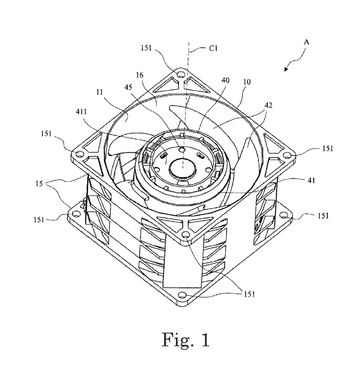
[0023]Hereinafter, preferred embodiments of the present disclosure will be described in detail with reference to the accompanying drawings. It is assumed herein that, regarding an axial fan A, a direction parallel to a central axis C1 of the axial fan A is referred to by the term “axial direction”, “axial”, or “axially”, that directions perpendicular to the central axis C1 of the axial fan A are each referred to by the term “radial direction”, “radial”, or “radially”, and that a direction along a circular arc centered on the central axis C1 of the axial fan A is referred to by the term “circumferential direction”, “circumferential”, or “circumferentially”. It is also assumed herein that, regarding the axial fan A, an axial direction is a vertical direction, and that a side on which an air inlet 16 of a housing 10 is arranged with respect to an impeller 40 is defined as an upper side. The shape of each member or portion and relative positions of different members or portions will be ...


PUM


Abstract

An axial fan includes a rotor portion, a stator portion arranged radially opposite to the rotor portion, and an impeller hub fixed to the rotor portion, and arranged to be capable of rotating integrally with the rotor portion. The impeller hub includes a hub top plate portion; a hub tubular portion being tubular, and arranged to extend axially downward from an outer edge of the hub top plate portion; a plurality of blades arranged in a circumferential direction; a plurality of wall portions arranged in the circumferential direction radially inside of the hub tubular portion; and a joining portion arranged to join a corresponding one of the wall portions to the hub tubular portion. A radially outer surface of the rotor tubular portion is arranged to be in contact with an inner surface of at least one of the wall portions.

Description

CROSS REFERENCE TO RELATED APPLICATIONS[0001]This application claims the benefit of priority to Japanese Patent Application No. 2017-187684 filed on Sep. 28, 2017. The entire contents of this application are hereby incorporated herein by reference.BACKGROUND OF THE INVENTION1. Field of the Invention[0002]The present disclosure relates to an axial fan.2. Description of the Related Art[0003]In a known fan, an impeller is attached to a rotor yoke. The impeller includes an impeller cup including a tubular lateral wall portion in the shape of a truncated cone, and a plurality of blades arranged in an annular shape and arranged to project from an outer circumferential surface of the lateral wall portion of the impeller cup. In addition, inside of the lateral wall portion of the impeller cup, an annular member is defined concentrically and integrally with the lateral wall portion of the impeller cup. A plurality of support members are arranged in a circumferential direction between an inne...

Claims


Application Information

Patent Timeline
IPC IPC(8): F04D29/32F04D29/053
CPCF04D29/329F04D29/053F04D25/0613F04D29/263
Inventor INOUCHI, KAZUHIROTATARA, TATSUYAMATSUYAMA, JUNYA
Owner NIDEC CORP
Why Eureka
Eureka Blog
Learn More