Fixed focal length lens and image pickup apparatus

Active Publication Date: 2019-04-04
CANON KK
View PDF0 Cites 4 Cited by
  • Summary
  • Abstract
  • Description
  • Claims
  • Application Information

AI Technical Summary

Benefits of technology

[0004]The present invention provides, for example, a fixed focal length lens advantageous i

Problems solved by technology

However, unless the power of each unit is appropriately set, it is not possible to compatibly realize both a substantially unifo

Method used


Image

  • Fixed focal length lens and image pickup apparatus
  • Fixed focal length lens and image pickup apparatus
  • Fixed focal length lens and image pickup apparatus

Examples


embodiment 1

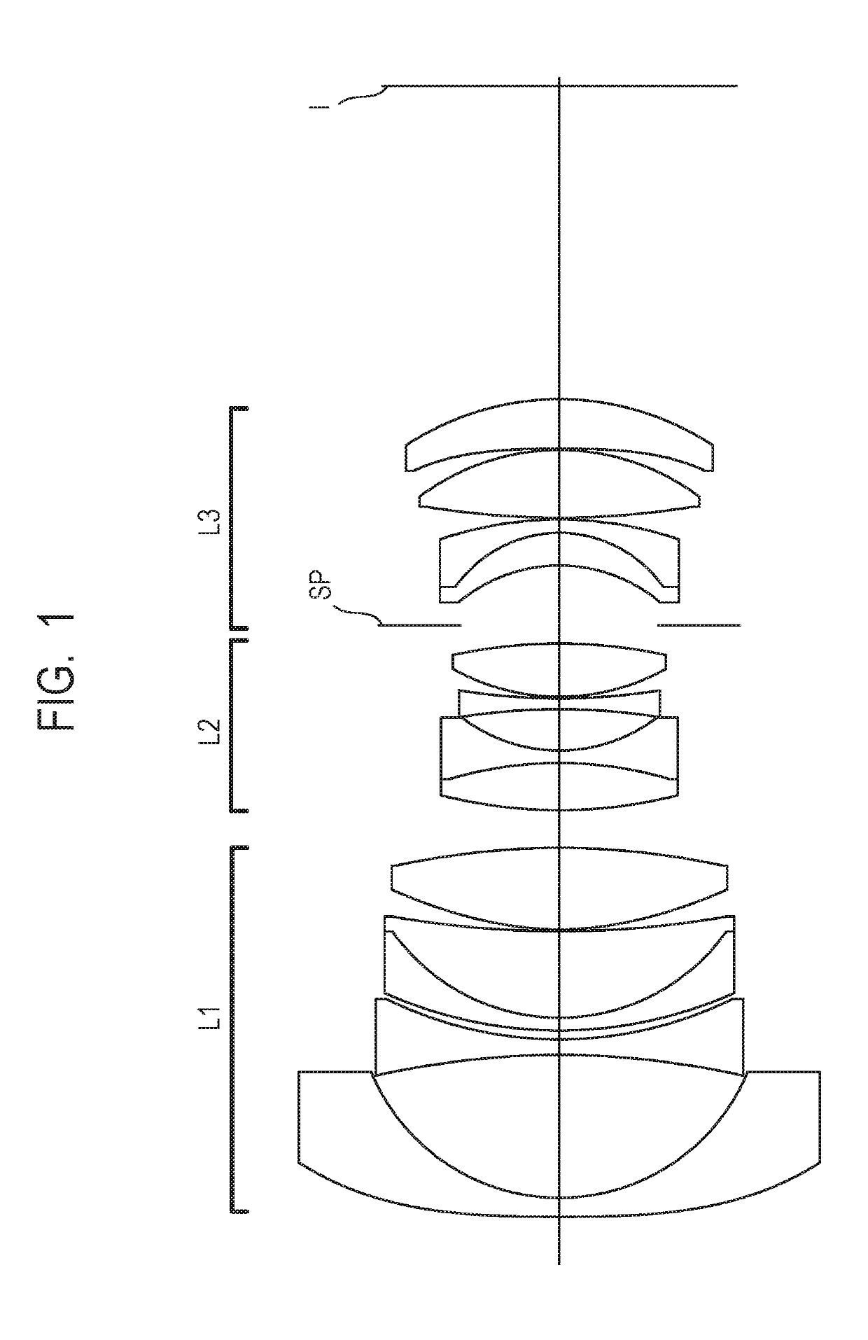
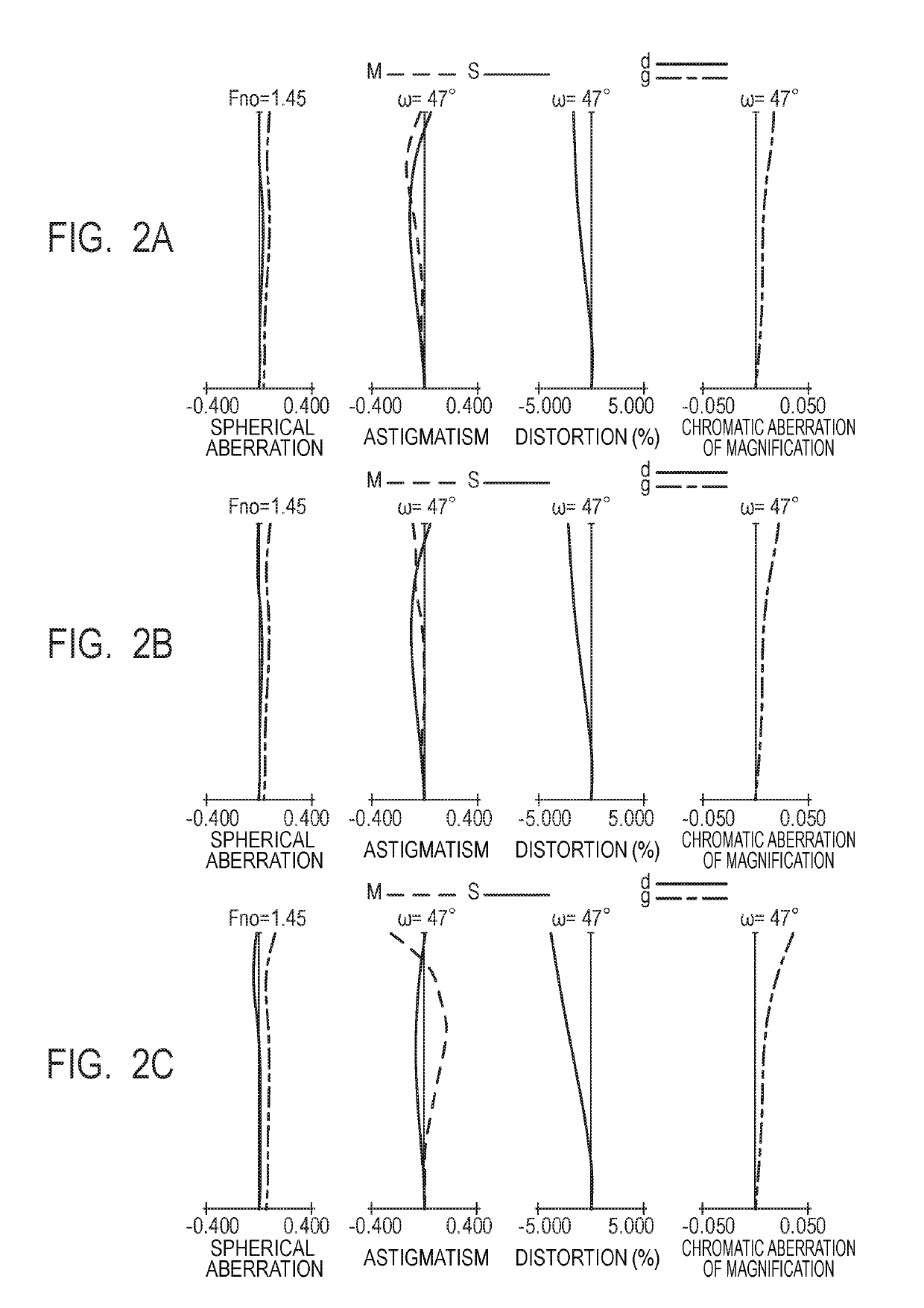
[0060]FIG. 1 is a cross-sectional view of lenses when focused at infinity in a fixed focal length lens that is Embodiment 1 (Numerical Embodiment 1) of the present invention. FIGS. 2A, 2B and 2C illustrate longitudinal aberration graphs when focused on an object at infinity, 1.0 m and 0.3 m, respectively. The values of the focal lengths are values when a numerical embodiment that is described later is expressed in mm units. The same also applies with respect to the numerical embodiments described hereunder.

[0061]In FIG. 1, the fixed focal length lens has, in order from an object side to an image side, a first lens unit L1 having a positive refractive power that does not move for focusing, and furthermore, a second lens unit L2 having a positive refractive power that moves to the object side when shifting focus to a nearby object from infinity, and a third lens unit L3 having a positive refractive power that, when shifting focus to a nearby object from infinity, moves to the object s...

embodiment 2

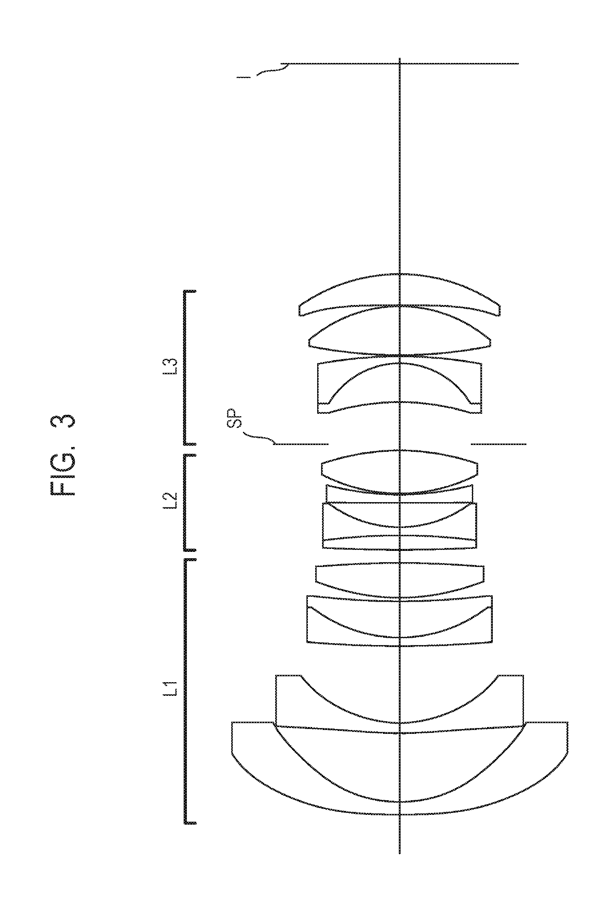
[0068]FIG. 3 is a cross-sectional view of lenses when focused at infinity in a fixed focal length lens that is Embodiment 2 (Numerical Embodiment 2) of the present invention. FIGS. 4A, 4B and 4C illustrate longitudinal aberration graphs when focused on an object at infinity, 1.0 m and 0.3 m, respectively.

[0069]In FIG. 3, the fixed focal length lens has, in order from an object side to an image side, a first lens unit L1 having a positive refractive power that does not move for focusing, and furthermore, a second lens unit L2 having a positive refractive power that, when shifting focus to a nearby object from infinity, moves to the object side, and a third lens unit L3 having a positive refractive power that, when shifting focus to a nearby object from infinity, moves to the object side by a movement amount that is different from a movement amount of the second lens unit L2.

[0070]Next, the first lens unit L1 of the present embodiment will be described. The first lens unit L1 correspo...

embodiment 3

[0072]FIG. 5 is a cross-sectional view of lenses when focused at infinity in a fixed focal length lens that is Embodiment 3 (Numerical Embodiment 3) of the present invention. FIGS. 6A, 6B and 6C illustrate longitudinal aberration graphs when focused on an object at infinity, 1.0 m and 0.3 m, respectively.

[0073]In FIG. 5, the fixed focal length lens has, in order from an object side to an image side, a first lens unit L1 having a positive refractive power that does not move for focusing, and furthermore, a second lens unit L2 having a positive refractive power that, when shifting focus to a nearby object from infinity, moves to the object side, and a third lens unit L3 having a positive refractive power that, when shifting focus to a nearby object from infinity, moves to the object side by a movement amount that is different from a movement amount of the second lens unit L2.

[0074]Next, the first lens unit L1 of the present embodiment will be described. The first lens unit L1 correspo...


PUM


Abstract

A fixed focal length lens includes, in order from an object side, a first lens unit having a positive refractive power, a second lens unit having a positive refractive power and a third lens unit having a positive refractive power, the second lens unit and the third lens unit moving for focusing differently from each other to change a distance between each pair of adjacent lens units changes. The first lens unit includes, in order from the object side to the image side, a first lens having a negative refractive power and a second lens having a negative refractive power. A focal length of the fixed focal length lens in a case of focusing on an object at infinity, a focal length of the first lens unit, a focal length of the second lens unit and a focal length of the third lens unit are appropriately set.

Description

BACKGROUND OF THE INVENTIONField of the Invention[0001]The present invention relates to a fixed focal length lens and an image pickup apparatus.Description of the Related Art[0002]Among image pickup apparatuses such as photographic cameras, movie cameras and video cameras, there is a need, in particular, for image pickup optical systems that have a wide angle of view which are used in single-lens reflex cameras or movie cameras to have a long back focus and to also have a substantially uniform resolving power from the center of the image plane to the periphery of the image plane over the entire object distance. Retrofocus-type image pickup optical systems are known as image pickup optical systems that have a wide angle of view and a long back focus. Among these, focus adjustment systems are know that, when adjusting the focus from an object at infinity to a nearby object, use so-called “floating” that causes two units at the rear in the optical system to move to the object side by m...

Claims


Application Information

Patent Timeline
IPC IPC(8): G02B13/04G02B9/12G02B7/04G02B9/34G02B13/18
CPCG02B13/04G02B9/12G02B7/04G02B9/34G02B13/18G02B9/64G02B5/005
Inventor YUKI, AKIHIKOKIKUCHI, SHOHEI
Owner CANON KK
Why Eureka
Try Eureka