Modular Data Acquisition System

a data acquisition and module technology, applied in the field of module data acquisition systems, can solve the problems of requiring time and skill to ensure the module, not facilitating other uses, and comparatively cumbersom

Inactive Publication Date: 2019-04-04
DEFENCE INNOVATIONS IP PTY LTD
View PDF0 Cites 0 Cited by
  • Summary
  • Abstract
  • Description
  • Claims
  • Application Information

AI Technical Summary

Benefits of technology

[0009]Preferably, the physical contact between adjacent modules in the data acquisition system is adapted to enable acoustic waves to transmit therethrough, with minimal loss of fidelity and minimal attenuation to the acoustic waves.
[0012]Preferably, the shape of the first side wall, and the shape of the second side wall, in each module, is uniform, in both size and shape, and includes additional projections, either upon each respective face, or around the periphery of the respective side walls, that are complimentary, and help to ensure the proper orientation of each adjacent pair of modules, and help to guide the at least one extension member into its corresponding void.
[0014]Alternatively, emerging forms of wireless power supply means are used to power individual modules, thereby eliminating the need for a dedicated physical electrical bus and electrical inter-connector.

Problems solved by technology

In all cases, these latches, if used, provided only mechanical locking only, and do not facilitate other uses, such as the interconnection of data or power connection.
There are several significant problems with this type of system.
Firstly, the plethora of cables that are used to interconnect the modules used at any time in the data acquisition system, is comparatively cumbersome, and requires time and skill to ensure the modules are cabled together properly.
Further, each cable interconnect is a potential mode of failure between two modules, and this may incapacitate the entire system.
In addition, the plurality of cable connectors may not be able to meet rigorous military standards governing vibration resistance for both land and aerospace vehicles.
The cables may be easily snagged when the unit is being installed, and / or reconfigured, and this may be another mode of failure.
The act of snagging may damage the cable connector, and may render the module non-functional, and requiring repair.
In many applications for such systems, particularly in aerospace vehicle applications, the space available for the data acquisition system is extremely limited.
This arrangement does away with the multiple cable interconnections, and can also be designed to be more compact, however it introduces other problems.
Firstly, the data acquisition system is limited by the finite number of slots within any particular housing.
This is time consuming and inefficient, and prevents “hot swapping” of modules.
Further to this, there is another significant problem associated with the physical constraints on the size of each module that is able to be inserted into the available slots.
The module cannot be so big that it interferes with access to a neighbouring slot within the housing.

Method used


Image

  • Modular Data Acquisition System
  • Modular Data Acquisition System
  • Modular Data Acquisition System

Examples


Embodiment Construction

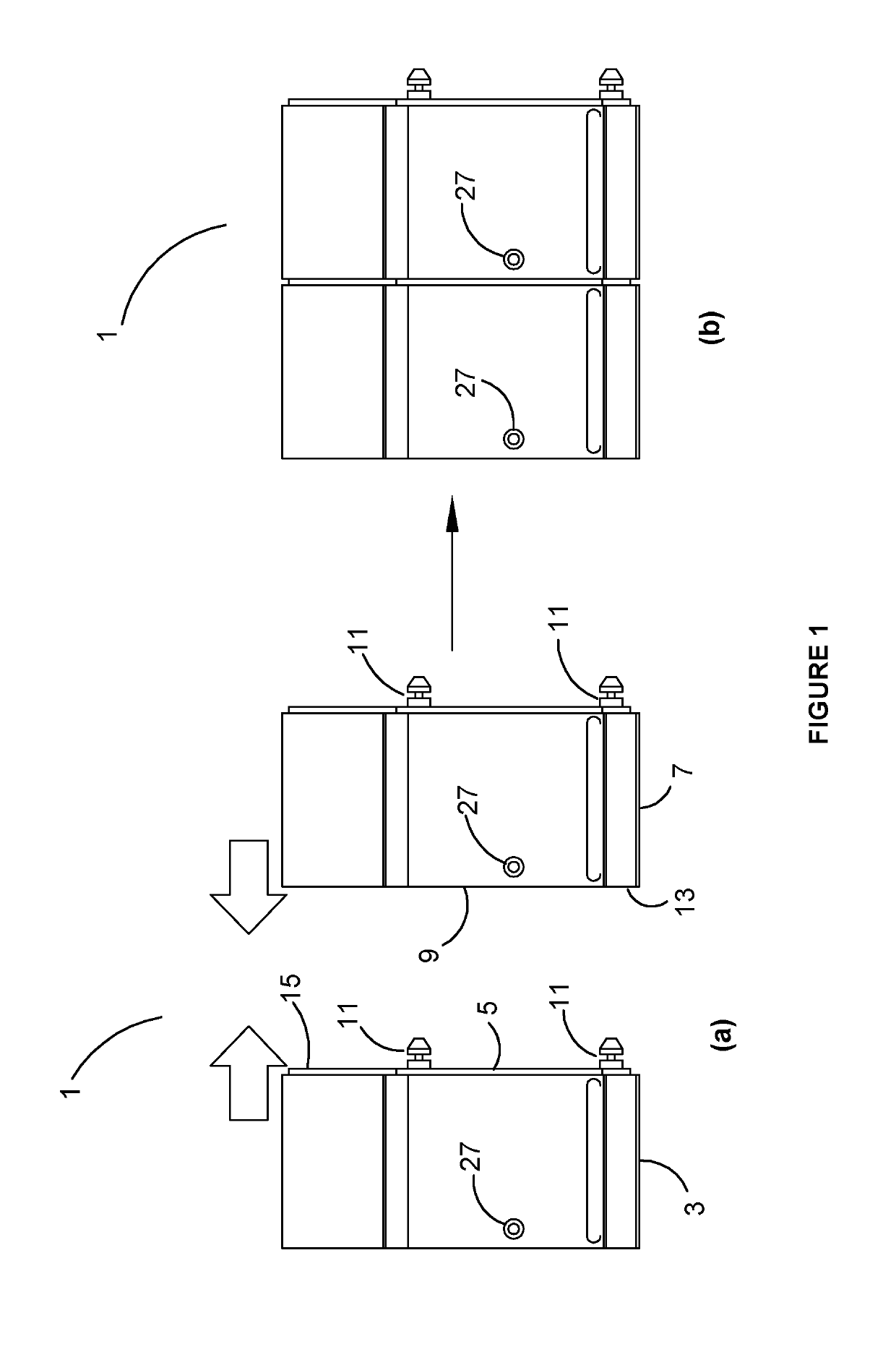
[0024]FIGS. 1 (a) and (b) show two modules ready to be interconnected in one form of the present invention.

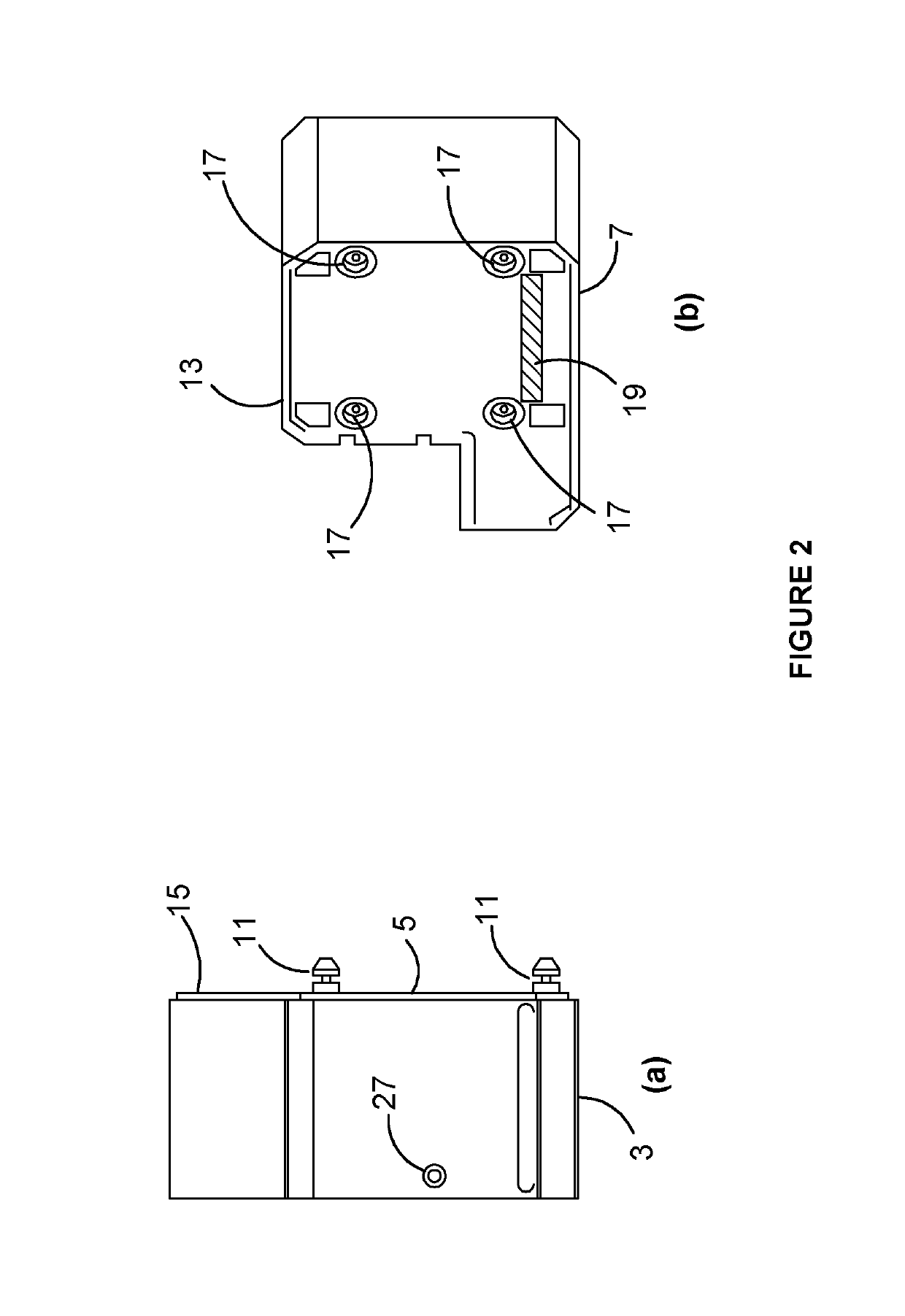
[0025]FIGS. 2 (a) and (b) show side views of a module used in accordance with one form of the present invention.

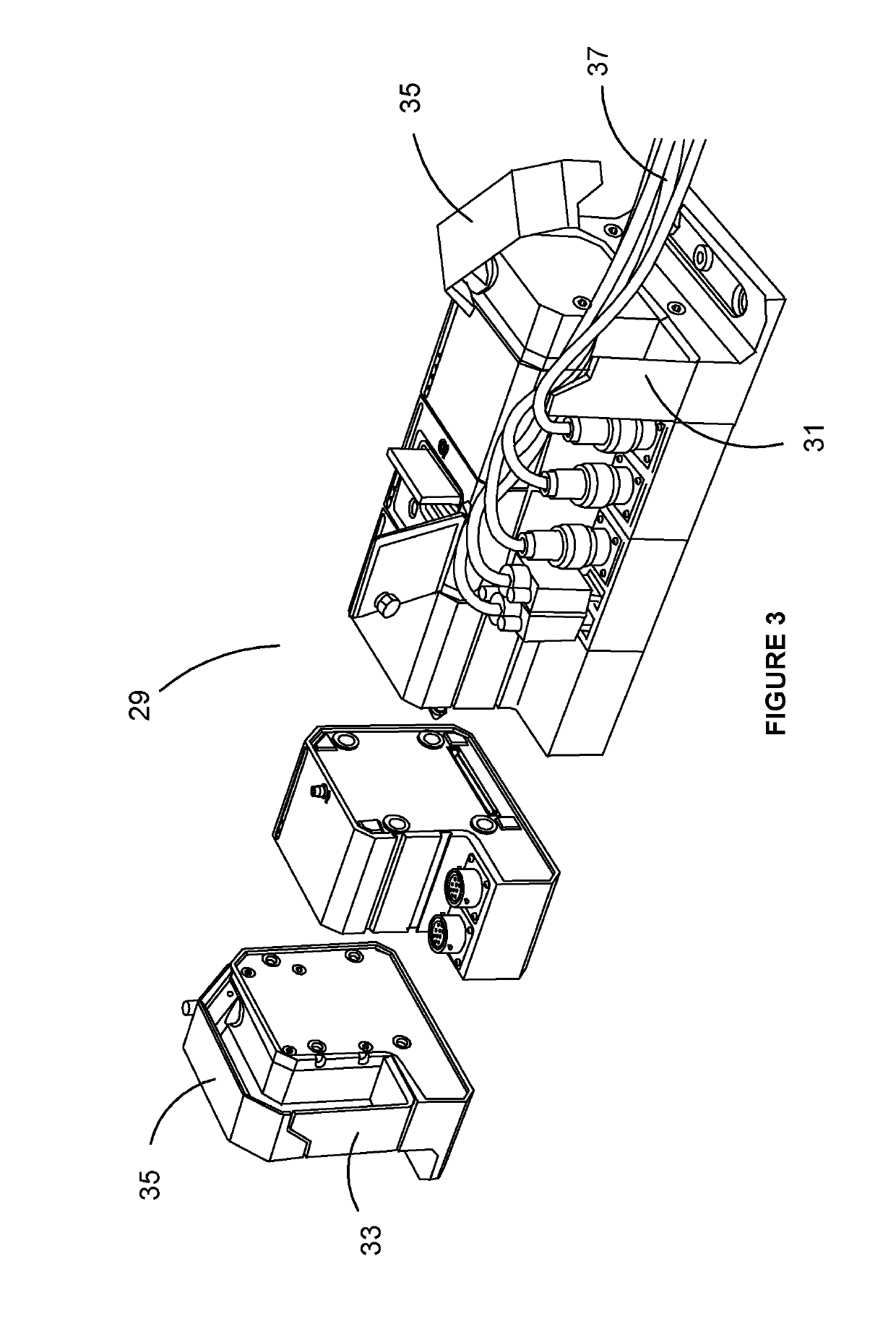
[0026]FIG. 3 shows an isometric view of a typical data acquisition system in accordance with he present invention, partially assembled.

DETAILED DESCRIPTION OF PREFERRED EMBODIMENTS OF THE PRESENT INVENTION

[0027]Turning firstly to FIG. 1, we are shown an embodiment of the present invention where the data acquisition system 1 as illustrated, includes first module 3 having a first side face 5 and a second module 7 having a second side face 9. In this embodiment, the first face 5 includes a plurality of pins 11. The arrows indicate that the adjacent modules are moved into physical contact with one another so that the first face 5 is physically in contact with the second face 9. In this embodiment, the second face includes a skirt 13 that is arranged around the periphery o...


PUM


Abstract

The present invention is a mobile modular data acquisition system including at least one module, and interconnect means, that are adapted to connect a pair of adjacent modules, in the data acquisition system together. Each module in the data acquisition system includes a first face, and a second face, that is located opposite to the first face, and when two modules are placed side by side and connected together, the first face of the first module is in physical contact with the second face of the second module. Preferably, when two modules are connected together, there is an electrical connection path between the modules.

Description

SCOPE OF THE INVENTION[0001]The present invention relates to modular data acquisition systems.BACKGROUND OF THE INVENTION[0002]There are plurality of modular data acquisition systems available. Some of these are characterized as being portable, and others are characterized as being ultra-portable. One example of such a system is the DATaRec 4 series by Zodiac Aerospace Systems. Systems such as these include a core unit with a variety of modules that may be added or removed from the data acquisition system to best service the needs of the system for any particular application. Each of the modules is self-contained, and is connected separately to an external power supply, and any data interconnection between separate modules in the system is done via external cabling. In some systems, adjacent modules may be physically latched together. In all cases, these latches, if used, provided only mechanical locking only, and do not facilitate other uses, such as the interconnection of data or ...

Claims


Application Information

Patent Timeline
Patent Type & Authority Applications(United States)
IPC IPC(8): G06F13/40G06F1/26
CPCG06F13/4081G06F1/266
Inventor CANNING, WARREN PETERLOK-KUN HO, DANIEL
Owner DEFENCE INNOVATIONS IP PTY LTD
Why Eureka
Try Eureka