
Exercise frame system

Active Publication Date: 2019-04-18
WATSON CORY
View PDF10 Cites 7 Cited by
  • Summary
  • Abstract
  • Description
  • Claims
  • Application Information

AI Technical Summary

Benefits of technology

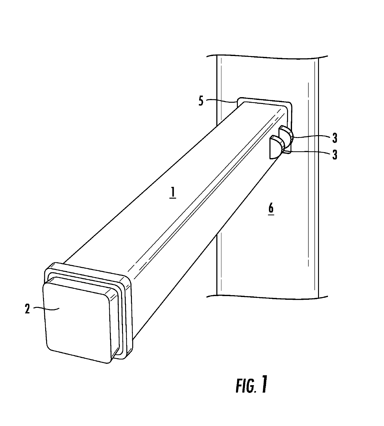
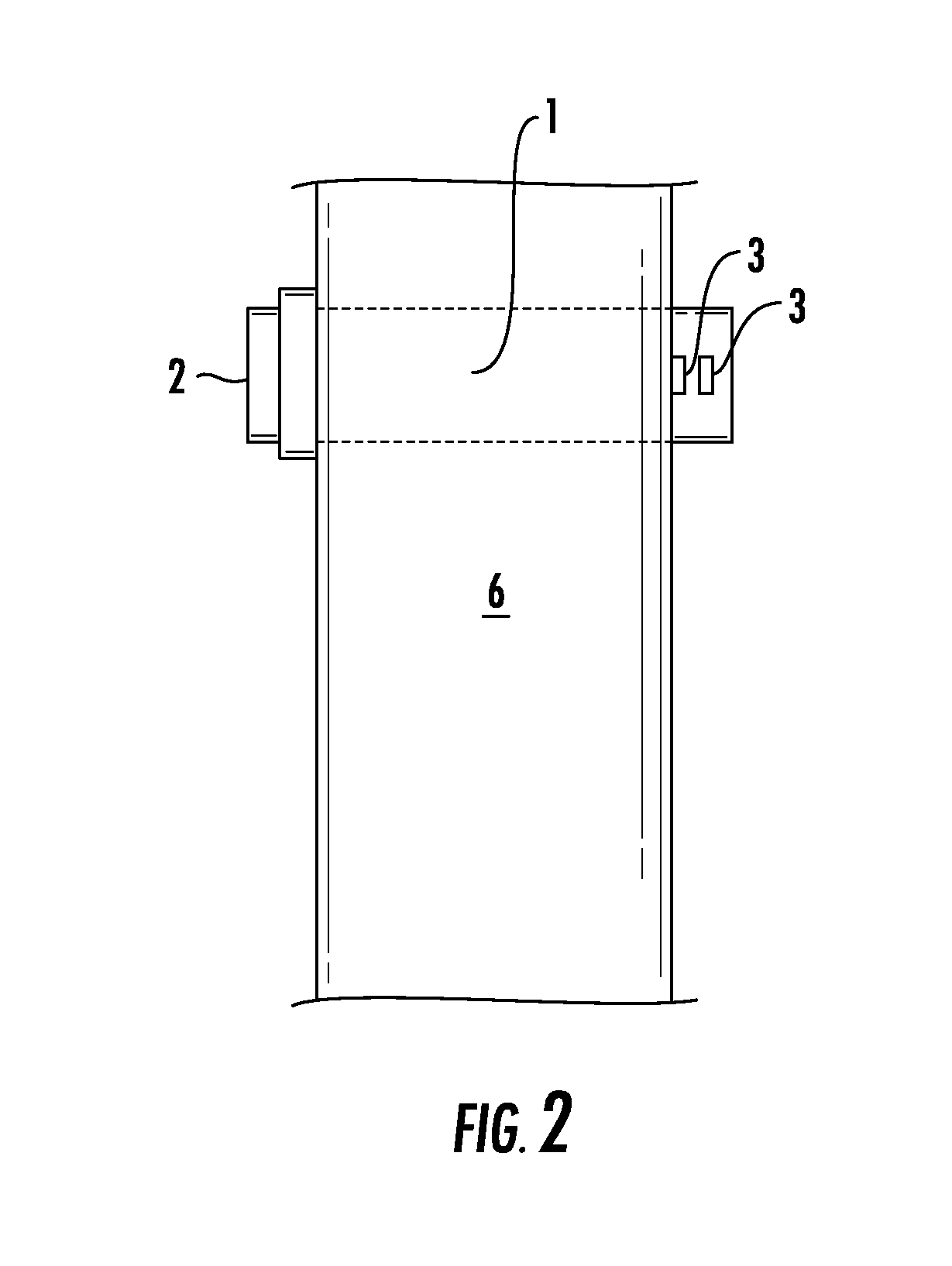
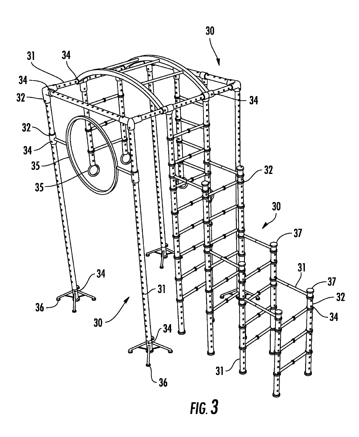
The present invention allows for interchangeable frames, adjustable height and length, and other improvements to the frame design. This is achieved by using flat sided attachment pegs in tubing and equipment, which makes the structure stronger and easier to assemble. The invention can also be used to change the overall design of the frame.

Problems solved by technology

While they work, they are still difficult to use, time consuming to use and do not always make for a steady holding in place of the connectors of the tubes or added on exercise equipment.
Connecting the parts of an exercise frame that is not permanent still has issues of stability that require new solutions.

Method used


Image

  • Exercise frame system
  • Exercise frame system
  • Exercise frame system

Examples


Embodiment Construction

[0015]While this invention is susceptible to embodiment in many different forms, there is shown in the drawings and will herein be described in detail specific embodiments, with the understanding that the present disclosure of such embodiments is to be considered as an example of the principles and not intended to limit the invention to the specific embodiments shown and described. In the description below, like reference numerals are used to describe the same, similar or corresponding parts in the several views of the drawings. This detailed description defines the meaning of the terms used herein and specifically describes embodiments in order for those skilled in the art to practice the invention.

Definitions

[0016]The terms “about” and “essentially” mean±10 percent.

[0017]The terms “a” or “an”, as used herein, are defined as one or as more than one. The term “plurality”, as used herein, is defined as two or as more than two. The term “another”, as used herein, is defined as at leas...


PUM


Abstract

The present invention discloses a new, more stable locking pin system for use in constructing adjustable exercise machine designs.

Description

COPYRIGHT NOTICE[0001]A portion of the disclosure of this patent contains material that is subject to copyright protection. The copyright owner has no objection to the reproduction by anyone of the patent document or the patent disclosure as it appears in the Patent and Trademark Office patent files or records, but otherwise reserves all copyright rights whatsoever.BACKGROUND OF THE INVENTIONField of the Invention[0002]The present invention relates to lock pins for exercise frame type systems. In particular, it relates to a locking pin system for use in home and commercial exercise frame type systems and applications for connectors and add on devices.Description of Related Art[0003]The use of a frame to support exercise positions are well known. Children's constructions are well known as jungle gyms and frames designed for adult use are called climbing frames or exercise frames. They are all basically a frame of metal or plastic designed to support the weight of the individual using...

Claims


Application Information

Patent Timeline
IPC IPC(8): A63B9/00A63B71/02F16B21/12
CPCA63B9/00A63B71/023F16B21/12A63B2009/006A63B2225/093A63B2225/09A63B17/04A63B2208/12A63B2210/50F16B7/105F16B21/125F16B21/14
Inventor WATSON, CORY
Owner WATSON CORY
Learn More