Process for determining a remaining life for a gas turbine airfoil

a gas turbine and airfoil technology, applied in the direction of mechanical measuring arrangements, instruments, and mechanical means, can solve problems such as problems in the useful life of parts

Inactive Publication Date: 2008-06-17
FLORIDA TURBINE TECH
View PDF4 Cites 13 Cited by
  • Summary
  • Abstract
  • Description
  • Claims
  • Application Information

AI Technical Summary

Benefits of technology

[0009]The present invention is a process of determining if a used airfoil of a gas turbine engine has any remaining life, or if the airfoil is at or near its end of life period. The process involves determining the shape and material properties of an airfoil, modeling the airfoil and determining the residual stresses that would occur around the airfoil based upon proper operating conditions on the airfoil such as temperature loads, pressure loads, and other operating loads, observing the locations of cracks on the real airfoil, and then determining if a residual stress level would occur far enough into the wall of the airfoil to cause the crack to propagate enough weaken the structural strength of the airfoil such that the airfoil cannot be reused in the gas turbine engine. If the residual stresses that occur at the cracks observed on the surface of the airfoil do not pass into the wall of the airfoil enough to cause the cracks to propagate far, then the airfoil is considered to still have useful life and can be reused. The present invention is described for use in determining the useful life for an airfoil. However, the process could be used for any part in which cracks would cause problems in the useful life of the part.

Problems solved by technology

However, the process could be used for any part in which cracks would cause problems in the useful life of the part.

Method used


Image

  • Process for determining a remaining life for a gas turbine airfoil
  • Process for determining a remaining life for a gas turbine airfoil
  • Process for determining a remaining life for a gas turbine airfoil

Examples


Embodiment Construction

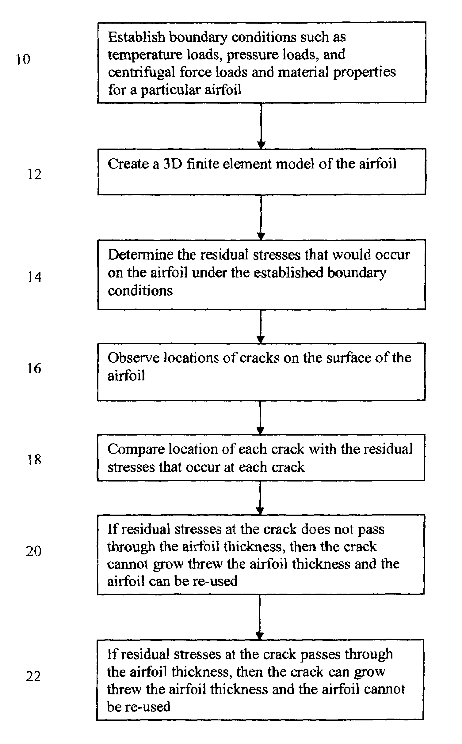
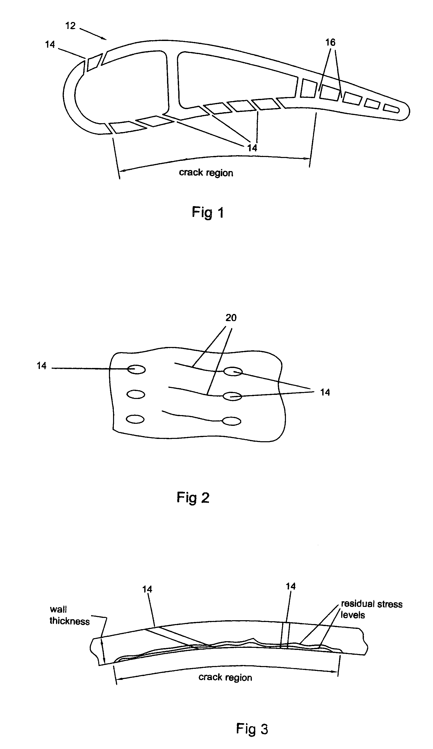
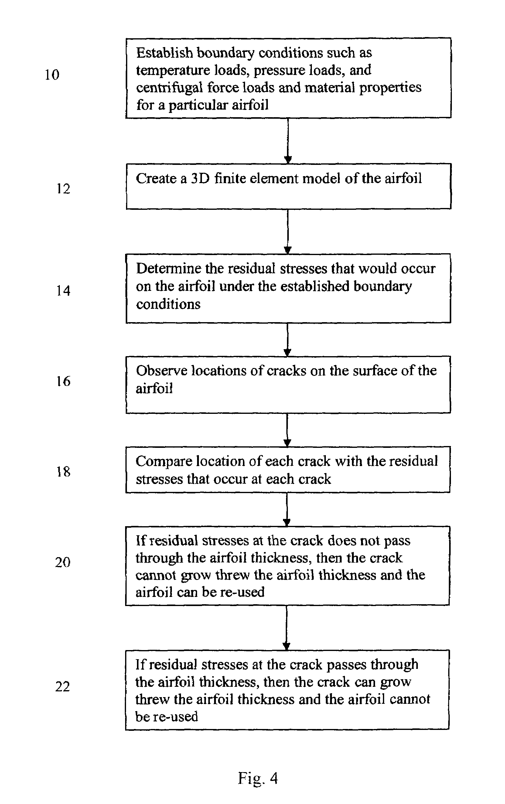
[0014]An airfoil cross section 12, such as a blade of a vane, used in a gas turbine engine is shown in FIG. 1. The airfoil includes a wall extending around the airfoil to define an outer airfoil surface, and a plurality of cooling holes 14 to discharge cooling air onto the airfoil surface for cooling purposes. The airfoil 12 includes ribs 16 located along the trailing edge and midway along the airfoil for structural purposes. FIG. 2 shows a side view of a portion of the airfoil on the pressure side in which a plurality of the cooling holes 14 are shown with cracks 20 propagating out from the holes 14. Cracks can occur at the cooling holes or away from the cooling holes. The cracks result from residual stresses that are formed on the airfoil wall from thermal material fatigue as the airfoil goes from operating temperature and conditions to an inoperative state at an ambient temperature. The cracks are most likely to form along a region on the pressure side of the airfoil identified b...


PUM

PropertyMeasurementUnit
residual stressesaaaaaaaaaa
residual stressaaaaaaaaaa
temperatureaaaaaaaaaa

Abstract

A process for determining a remaining life of a part, such as an airfoil in a gas turbine engine, comprising the steps of establishing the boundary conditions that act on the part, determining the material properties of the part, creating a 3D finite element model of the part and determining the residual stresses on the part, observing the actual part for cracks, and comparing the location of the crack to the residual stresses determined on the model at the crack location. If the residual stress at the crack location passes into the wall of the part beyond a predetermined length, then the part is rejected for further use.

Description

CROSS-REFERENCE TO RELATED APPLICATIONS[0001]This application claims the benefit to an earlier filed U.S. Provisional application Ser. No. 60 / 783,651 filed on Mar. 17, 2006 and entitled PROCESS FOR DETERMINING A REMAINING LIFE FOR A GAS TURBINE AIRFOIL.STATEMENT REGARDING FEDERALLY SPONSORED RESEARCH OR DEVELOPMENT[0002]None.BACKGROUND OF THE INVENTION[0003]1. Field of the Invention[0004]The present invention relates to a process of determining a remaining life for a part, and more specifically to determining a remaining life for an airfoil used in the gas turbine engine.[0005]2. Description of the Related Art Including Information Disclosed Under 37 CFR 1.97 and 1.98[0006]Industrial gas turbine engines (and even aero gas turbine engines) use several stages of blades and vanes in the turbine section of the engine that are under high temperature loads as well as mechanical loads. The airfoils include cooling air holes opening onto the outer surface of the airfoils for passing cooling...

Claims


Application Information

Patent Timeline
Patent Type & Authority Patents(United States)
IPC IPC(8): G01N3/32
CPCG01M5/0033G01M13/00
Inventor DELANEUVILLE, ROBERT E.
Owner FLORIDA TURBINE TECH
Why Eureka
Try Eureka