
Sealing Device

a sealing device and sealing strip technology, applied in the direction of building components, wing arrangements, construction, etc., can solve the problems reducing the sealing effect, and increasing the effort of the sealing strip, so as to achieve the effect of reducing the sealing strip and increasing the effor

Active Publication Date: 2019-05-02
ASSA ABLOY AB
View PDF8 Cites 4 Cited by
  • Summary
  • Abstract
  • Description
  • Claims
  • Application Information

AI Technical Summary

Benefits of technology

The sealing device described in this patent has a bearing face that helps keep the door leaf in place without needing additional force. This allows for the sealing strip to seal the door in an optimal way while also preventing excessive pressure on the body. The device is also tolerant to both vertical and horizontal tolerances, making assembly easier and more time-efficient.

Problems solved by technology

This assembly has the disadvantage that a relatively great effort in terms of force by the user is necessary in the closing of the door, because the slide has to be lowered counter to the spring force and to the resistance of the lever that pushes onto the activation button.
It is also disadvantageous that the automatic lifting of the slide in the opening of the door leads to the door being opened in a self-acting manner, the user thus not keeping full control in the opening action.
A further disadvantage is that the slide in the running direction of the sliding door is disposed behind the drop-down seal such that the sealing strip has to be configured in a shortened manner and cannot completely seal in the region of the secondary closing edge.
The use of drop-down seals of this type in sliding doors is more problematic since the transmission of force onto the activation button is only 1:1 and thus more force has to be applied in order for the activation button to also be depressed in the closing of the door leaf.

Method used


Image

  • Sealing Device
  • Sealing Device
  • Sealing Device

Examples


Embodiment Construction

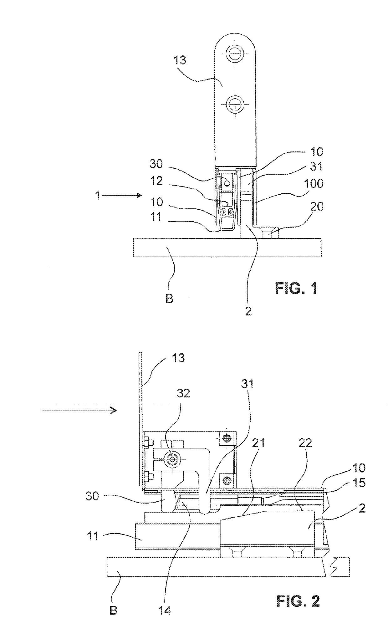
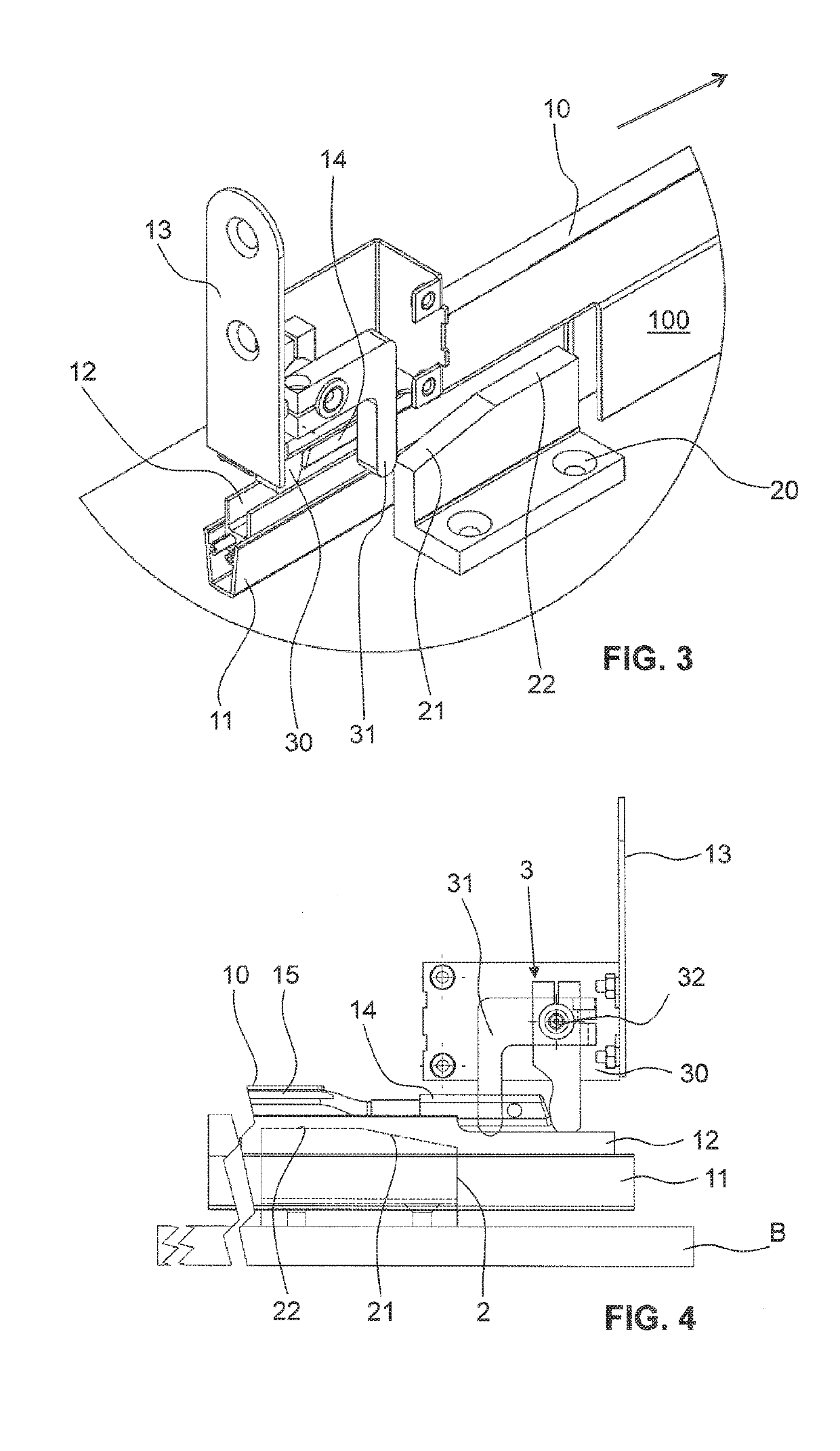
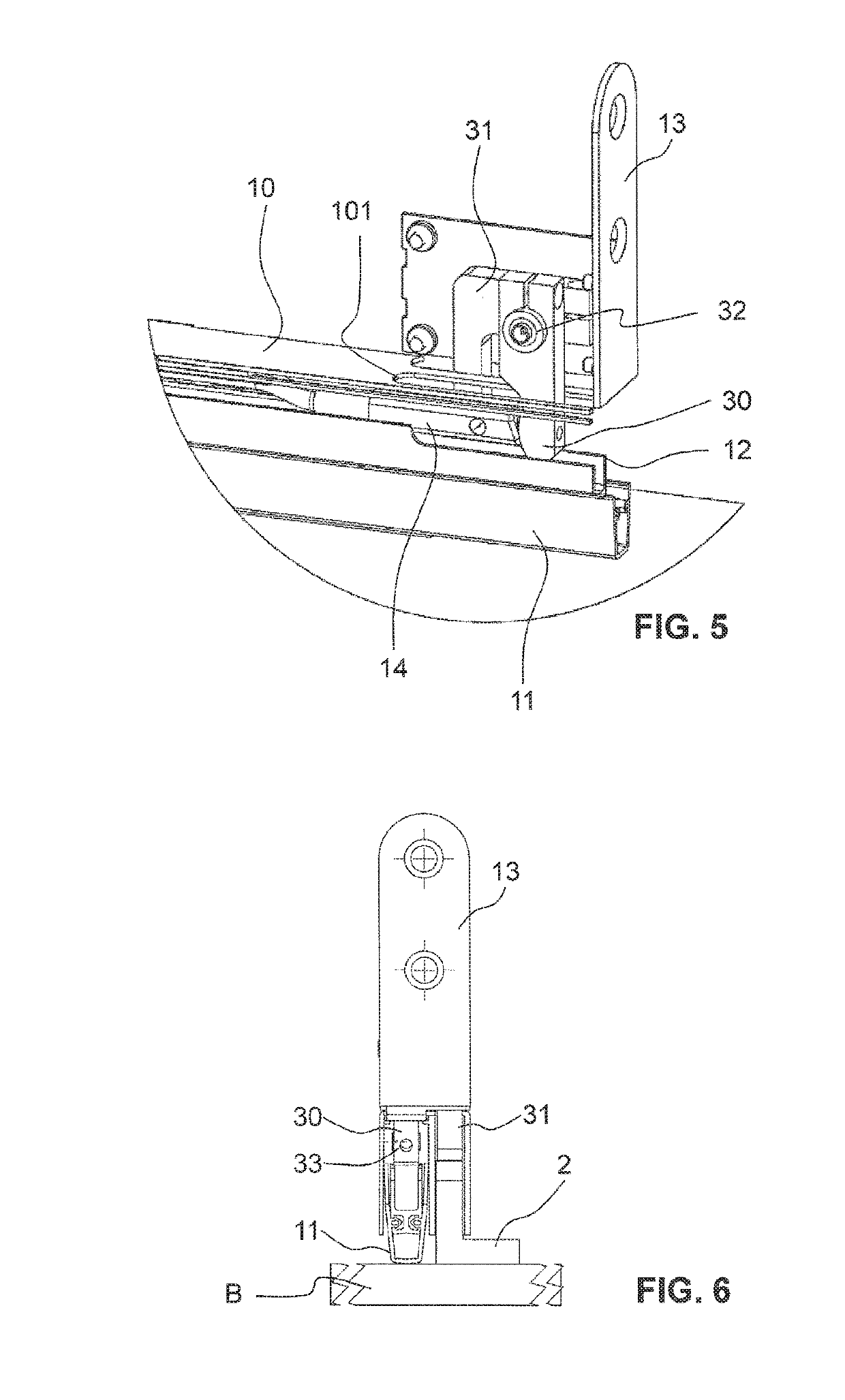
[0072]FIGS. 1 to 10 show a first exemplary embodiment of a sealing device according to the invention.

[0073]The sealing device has a drop-down seal 1 of a known type, such as has been described at the outset, for example. The drop-down seal 1 has a housing rail 10 which by means of known means, here by means of a fastening bracket 13 that at the end side is push-fitted into a groove of the housing rail 10, is fastened in a lower groove of a displaceable sliding door leaf. Other types of fastenings, for example by means of lateral clamps, are likewise possible. The drop-down seal in the lifted state is preferably flush with the lower side of the displaceable door leaf.

[0074]As opposed to the prior art, the housing rail 10 is not only configured in a hat-shaped or U-shaped manner while configuring a first chamber that is open toward the bottom. Said housing rail 10 preferably has a second chamber which is delimited by an external additional wall 100. A sealing strip is held so as to be...


PUM

PropertyMeasurementUnit
angleaaaaaaaaaa
angleaaaaaaaaaa
restoring forceaaaaaaaaaa

Abstract

A sealing device of a sliding door having a slidably mounted door leaf has a drop-down seal having a sealing strip and a lowering mechanism for automatically lowering and raising the sealing strip. The lowering occurs against a restoring force. The sealing device also has an activation unit for activating the drop-down seal. The activation unit has a contact surface, which is directed upward in the lowering direction, and a contact element, which lies against said contact surface during the closing of the door leaf and thereby actuates the drop-down seal. In this way, the weight of the door leaf can be used for the lowering of the sealing strip. Furthermore, a position in which the restoring force does not influence a sliding motion of the door leaf in the longitudinal direction of the sealing strip can be achieved.

Description

TECHNICAL FIELD[0001]The present invention relates to a sealing device for activating a drop-down seal, to a sliding door having a sealing device of this type, and to an activation unit of a sealing device of this type.PRIOR ART[0002]Drop-down seals are used for sealing doors and windows. Said drop-down seals prevent light from passing through and offer an acoustic protection as well as a protection against draft and smoke. In the case of external doors, said drop-down seals moreover serve as splash protection in the event of rain, and depending on the embodiment can also protect against flooding.[0003]Lowerable door and window seals are usually composed substantially of a housing in the form of a hat-shaped or U-shaped profiled rail that is open toward the bottom, a sealing strip that is held so as to be liftable and lowerable in said housing, said sealing strip having a sealing profile as well as an activation mechanism for lifting and lowering the sealing strip. The activation me...

Claims


Application Information

Patent Timeline
Patent Type & Authority Applications(United States)
IPC IPC(8): E06B7/21E06B7/215E06B7/23E06B3/46
CPCE06B7/21E06B7/215E06B7/2316E06B3/46E06B3/4636
Inventor DINTHEER, ANDREAS
Owner ASSA ABLOY AB
Learn More