Light raster microscope and its use

a light raster microscope and microscope technology, applied in the field ofconfocal laser scanning microscope, can solve the problems of certain difficulties in optical linking of the detector lying below the sampl

Inactive Publication Date: 2008-05-06
CARL ZEISS MICROSCOPY GMBH
View PDF12 Cites 2 Cited by
  • Summary
  • Abstract
  • Description
  • Claims
  • Application Information

AI Technical Summary

Benefits of technology

[0007]The objective of the invention is to extend a microscope of the type stated initially so that transmission measurements on the sample can be performed without increased effort.
[0017]A further advantage of the approach according to the invention lies in the fact that a transmitted light scan is also possible at several points, which customary, separate detectors disposed under the sample do not allow due to the lack of suitable spatial resolution. The use of a multi-point or point group scanner in transmitted light mode now opened up by the invention reduces any problems due to temporal fluctuations of the wide-field illumination since it can be compensated by suitable extension of the integration time in multi-point or point group systems. It is thus preferred that the wide-field illumination and the scanned point or point group illumination be performed simultaneously. Point group is understood to mean any arrangement of several points, in particular in the form of a line, which the laser scanning microscope confocally illuminates and images. Through this approach, further advantageously lower sample loads or shorter measuring times are realized, which in the state of the art were not possible in this manner. It is thus particularly preferred that the spot detector arrangement realizes a confocal point group imaging, for example, with at least one Nipkow disk and at least one matrix detector.

Problems solved by technology

The optical linking of the detector lying below the sample presents certain difficulties, in particular since one customarily also provides an optical viewing device for an observer on the microscope part of the laser scanning microscope.

Method used


Image

  • Light raster microscope and its use
  • Light raster microscope and its use
  • Light raster microscope and its use

Examples


Embodiment Construction

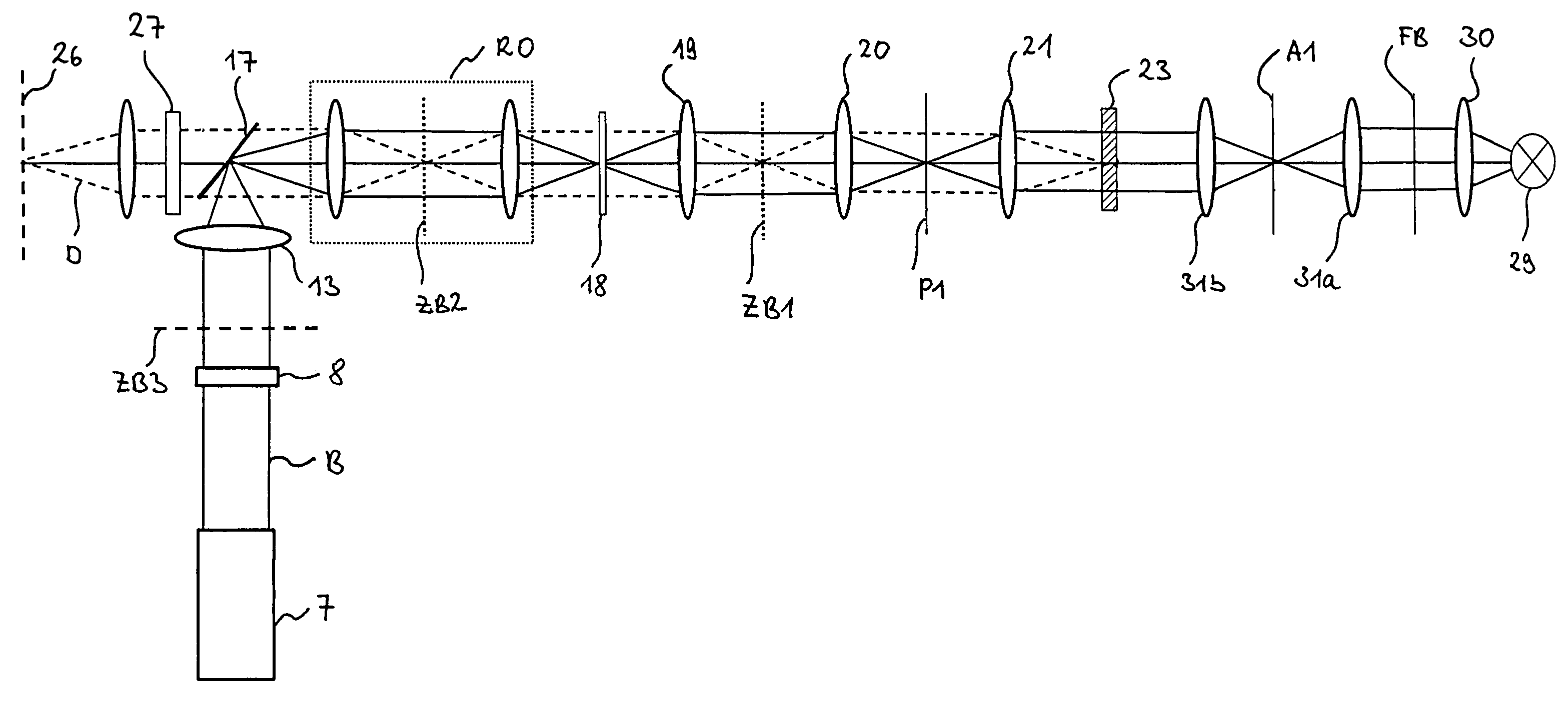
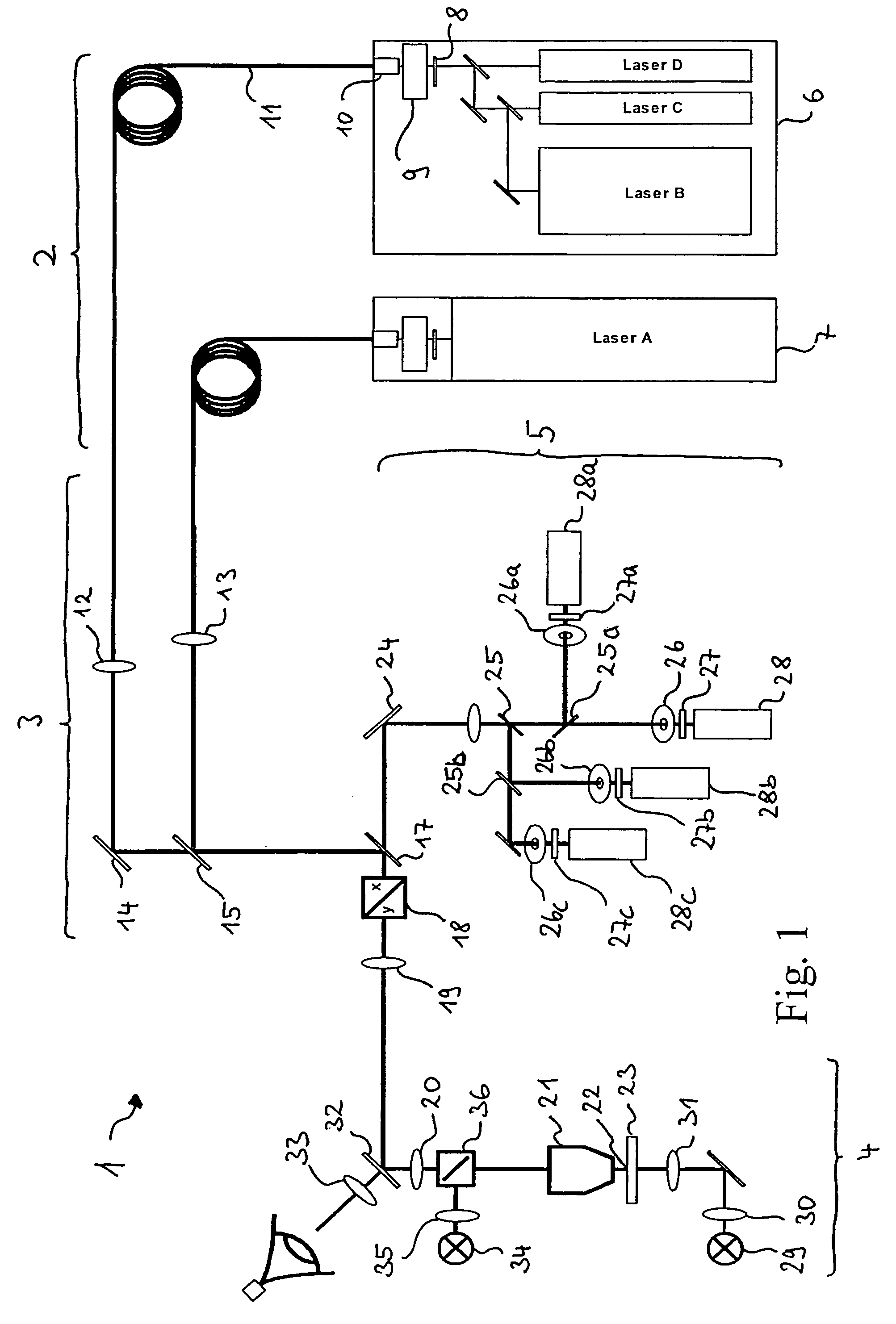
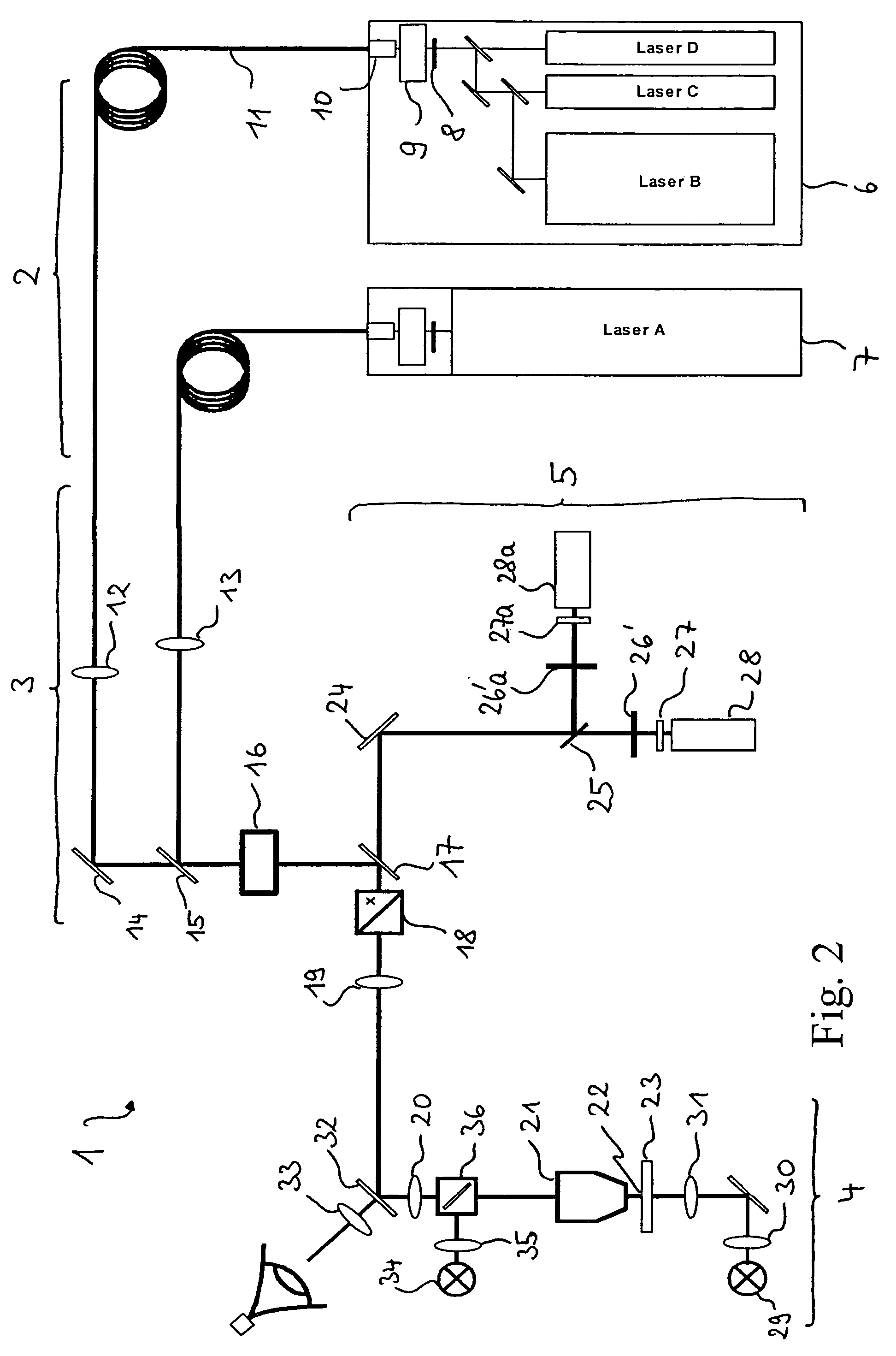
[0028]FIG. 1 shows schematically a laser scanning microscope 1 which is assembled essentially from five components: a radiation source module 2 which generates the excitation radiation for laser scanning microscopy, a scanning module 3 which conditions, and suitably deflects, the excitation radiation for scanning over the sample, a microscope module 4 which directs the scanning radiation provided by the scanning module in a microscopic beam path onto a sample, and a detector module 5 which receives and detects optical radiation from the sample. The detector module 5 can be implemented in this case, as is represented in FIG. 1, to have multiple spectral channels.

[0029]The radiation source module 2 generates illumination radiation which is suitable for laser scanning microscopy, therefore in particular radiation which can resolve fluorescence. Depending on the application, the radiation source module comprises several radiation sources for this purpose. In a form of embodiment represe...


PUM

PropertyMeasurementUnit
laser point scanning microscopeaaaaaaaaaa
transmission measurementaaaaaaaaaa
fluorescenceaaaaaaaaaa

Abstract

In a light raster scanning microscope with a spot illumination arrangement (2) which provides an illumination beam for the illumination of a sample (23) in the form of points or point groups, a scanning arrangement (3, 4) which guides the illumination beam in the form of points or point groups over the sample in a manner so as to scan, a spot detector arrangement (5) which images, via the scanning arrangement (3, 4), the illuminated point or point group spot of the sample (23) by means of at least one confocal aperture (26) on at least one detector unit (28), and a control unit which controls the scanning arrangement (3, 4) and reads out the spot detector arrangement (5), it is provided that, in addition, a wide-field illumination source (29, 34) is provided which illuminates the sample (23) and that the control unit controls the scanning arrangement (3, 4) during the operation of the wide-field illumination source (29, 34) and reads out the spot detector arrangement (5) in such a manner that an image of the sample (23) subject to wide-field illumination is obtained.

Description

BACKGROUND OF THE INVENTION[0001]1. Field of the Invention[0002]The invention relates to a confocal laser scanning microscope with a spot illumination arrangement which provides an illumination beam for the illumination of a sample by points or point groups, a scanning arrangement which guides the illumination beam by points or point groups over the sample in a manner so as to scan, a spot detector arrangement which images, via the scanning arrangement, the point or point group spot of the sample by means of at least one confocal aperture on at least one detector unit, and a control unit which controls the scanning arrangement and reads out the spot detector arrangement.[0003]The invention further relates to a process for laser scanning microscopy, wherein an image of a sample is generated by scanning and confocal imaging of a point or point group spot and means are provided for the illumination of the scanned point or point group spot.[0004]2. Related Art[0005]Confocal laser scanni...

Claims


Application Information

Patent Timeline
Patent Type & Authority Patents(United States)
IPC IPC(8): G02B21/06G01N21/00G02B21/00G02B21/14
CPCG02B21/0032G02B21/0064
Inventor WOLLESCHENSKY, RALF
Owner CARL ZEISS MICROSCOPY GMBH
Why Eureka
Try Eureka