Heat exchanger

a technology of heat exchanger and heat exchanger body, which is applied in the direction of indirect heat exchanger, lighting and heating apparatus, transportation and packaging, etc., can solve the problems of high possibility of valves being exposed to water and severe restrictions on arrangement spa

Active Publication Date: 2019-05-02
DENSO CORP
View PDF6 Cites 6 Cited by
  • Summary
  • Abstract
  • Description
  • Claims
  • Application Information

AI Technical Summary

Benefits of technology

[0008]According to the present disclosure, since at least a part of the refrigerant adjustment portion is inserted into the liquid reservoir, the liquid reservoir can work for protecting from water. In addition, connection between the refrigerant adjustment portion and various flow paths is also easy by using the liquid reservoir.

Problems solved by technology

However, if the heat exchanger and the liquid reservoir are disposed in a front part of the vehicle, there may be a high possibility that the valves are exposed to water, and some measures are required.
Also, especially when a refrigeration cycle is mounted on a moving body such as an automobile, restriction on arrangement space may be severe.

Method used


Image

  • Heat exchanger
  • Heat exchanger
  • Heat exchanger

Examples


Embodiment Construction

[0030]Hereinafter, the present embodiments will be described with reference to the attached drawings. In order to facilitate the ease of understanding, the same reference numerals are attached to the same constituent elements in each drawing where possible, and redundant explanations are omitted.

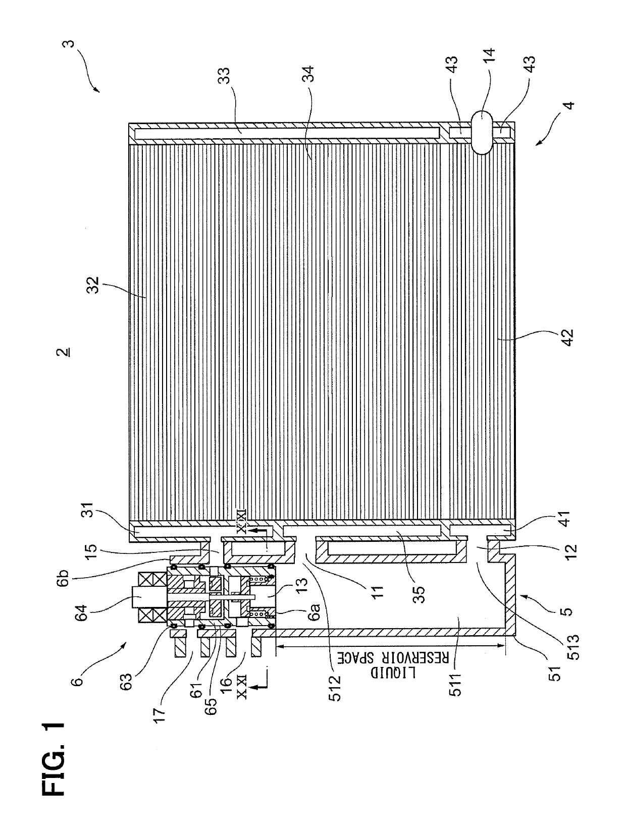
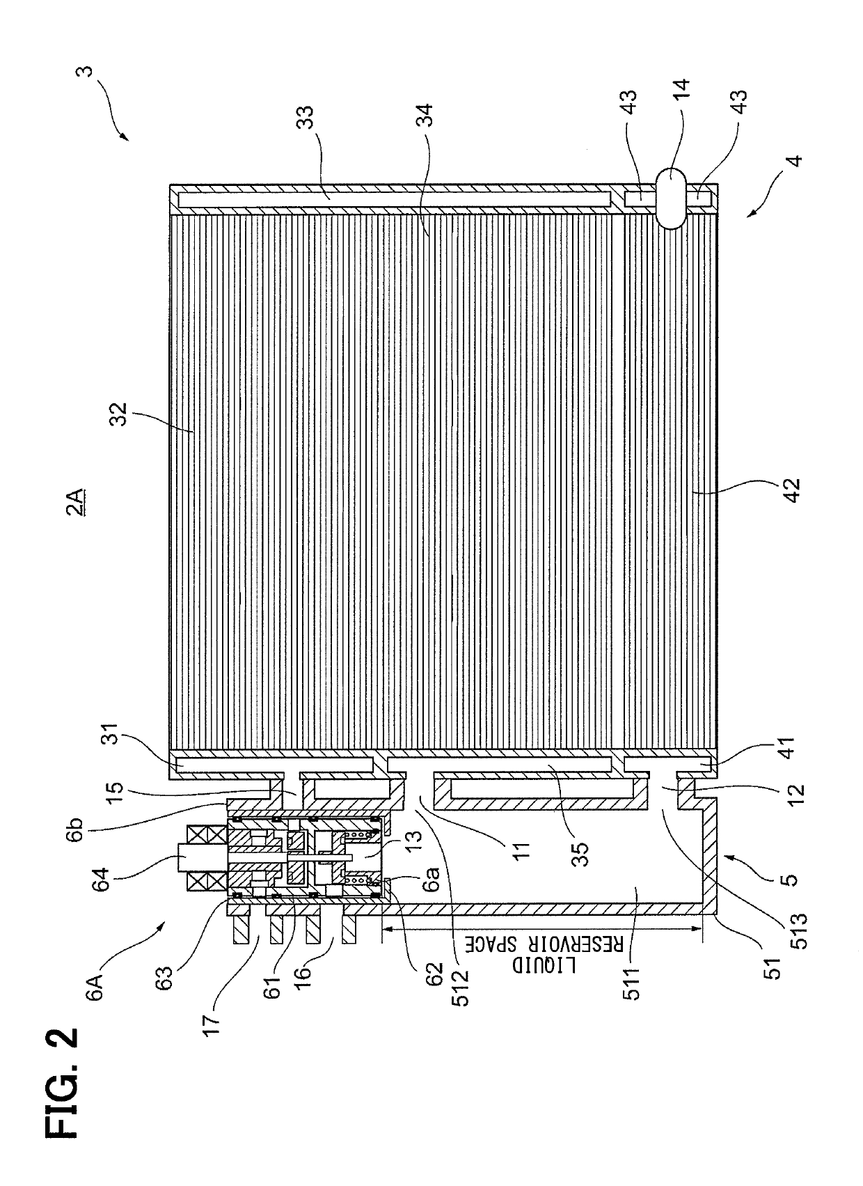
[0031]As shown in FIG. 1, a heat exchanger 2 according to a present embodiment includes an upstream heat exchanging portion 3, a downstream heat exchanging portion 4, and a liquid reservoir 5. The upstream heat exchanging portion 3 has two upstream cores 32, 34 and header tanks 31, 33, 35. In the present embodiment, the illustrated example is provided with two upstream cores 32, 34, but single core or three or more cores may be used. The upstream cores 32, 34 are parts that exchange heat between the refrigerant flowing therein and the air flowing outside, and includes tubes through which the refrigerant flows and fins provided between the tubes.

[0032]At the upstream end of the upstream core ...


PUM


Abstract

A heat exchanger includes: a heat exchanging portion configured to exchange heat between a refrigerant flowing through therein and air; a liquid reservoir configured to separate a gas-liquid two-phase refrigerant flowing out of the heat exchanging portion into a gas-phase refrigerant and a liquid-phase refrigerant, the liquid reservoir storing the liquid-phase refrigerant; and a refrigerant adjustment portion configured to adjust a flow state of the refrigerant flowing into the refrigerant adjustment portion through a refrigerant passage of the refrigeration cycle, supply the refrigerant to the heat exchanging portion and adjust an outflow state and an outflow destination of the refrigerant flowing out of the heat exchanging portion or the liquid reservoir. At least a part of the refrigerant adjustment portion is inserted into the liquid reservoir.

Description

CROSS REFERENCE TO RELATED APPLICATION[0001]This application is based on and claims the benefits of priority of Japanese Patent Application No. 2016-078226 filed on Apr. 8, 2016, and Japanese Patent Application No. 2017-070724 filed on Mar. 31, 2017, the entire disclosure of which is incorporated herein by reference.TECHNICAL FIELD[0002]The present disclosure relates to a heat exchanger.BACKGROUND ART[0003]Conventionally, for example as described in Patent Document 1 below, a refrigeration cycle device which uses this type of heat exchanger is known. The refrigeration cycle apparatus described in Patent Document 1 includes a gas-liquid separator for separating a refrigerant into a gas-phase refrigerant and a liquid-phase refrigerant, and a switching means for switching a refrigerant circuit, in which a refrigerant circulates, between a refrigerant circuit of a first mode and a refrigerant circuit of a second mode. Specifically, the gas-liquid separator separates the refrigerant flow...

Claims


Application Information

Patent Timeline
Patent Type & Authority Applications(United States)
IPC IPC(8): F25B39/04F25B43/00B60H1/32
CPCF25B39/04F25B43/00B60H1/3227B60H1/00335F25B2339/047F25B2600/25F28D2021/0084F25B2500/18F25B39/028F28F27/02F25B39/02F25B2339/0445
Inventor SUGIMURA, RYOHEIMIEDA, HIROSHIKAWAKUBO, MASAAKIKATO, DAIKIITO, TETSUYA
Owner DENSO CORP
Why Eureka
Try Eureka