Wafer susceptor

Pending Publication Date: 2019-05-02
NGK INSULATORS LTD
View PDF2 Cites 4 Cited by
  • Summary
  • Abstract
  • Description
  • Claims
  • Application Information

AI Technical Summary

Benefits of technology

The present invention relates to a wafer susceptor, which is used in semiconductor manufacturing equipment. The invention prevents loosening of an insulation pipe from a screw hole and ensures proper sealing with a sealing member. This is achieved by positioning the fore end surface of the sealing-member support portion of the insulation pipe at a predetermined position and pressing the sealing member between the plate-facing surface of the insulation pipe and the plate. Additionally, a screw locking adhesive may be applied to the screw hole to further prevent loosening of the insulation pipe.

Problems solved by technology

However, when the insulation pipe and the cooling-board penetrating portion are bonded to each other using the adhesive, it is difficult to fill the adhesive without leaving vacancies.
If the vacancies exist between the insulation pipe and the cooling-board penetrating portion, a problem arises in that the vacancies form conduction paths and insulation cannot be ensured.
Furthermore, in the case in which there is a difference in air pressure between the inside and the outside of the insulation pipe, the adhesive may be peeled off due to the difference in air pressure.
In addition, the insulation pipe and the cooling-board penetrating portion may be separated from each other due to repeated application of vibration and a moment of force during the use of the electrostatic chuck.

Method used


Image

  • Wafer susceptor
  • Wafer susceptor
  • Wafer susceptor

Examples


Embodiment Construction

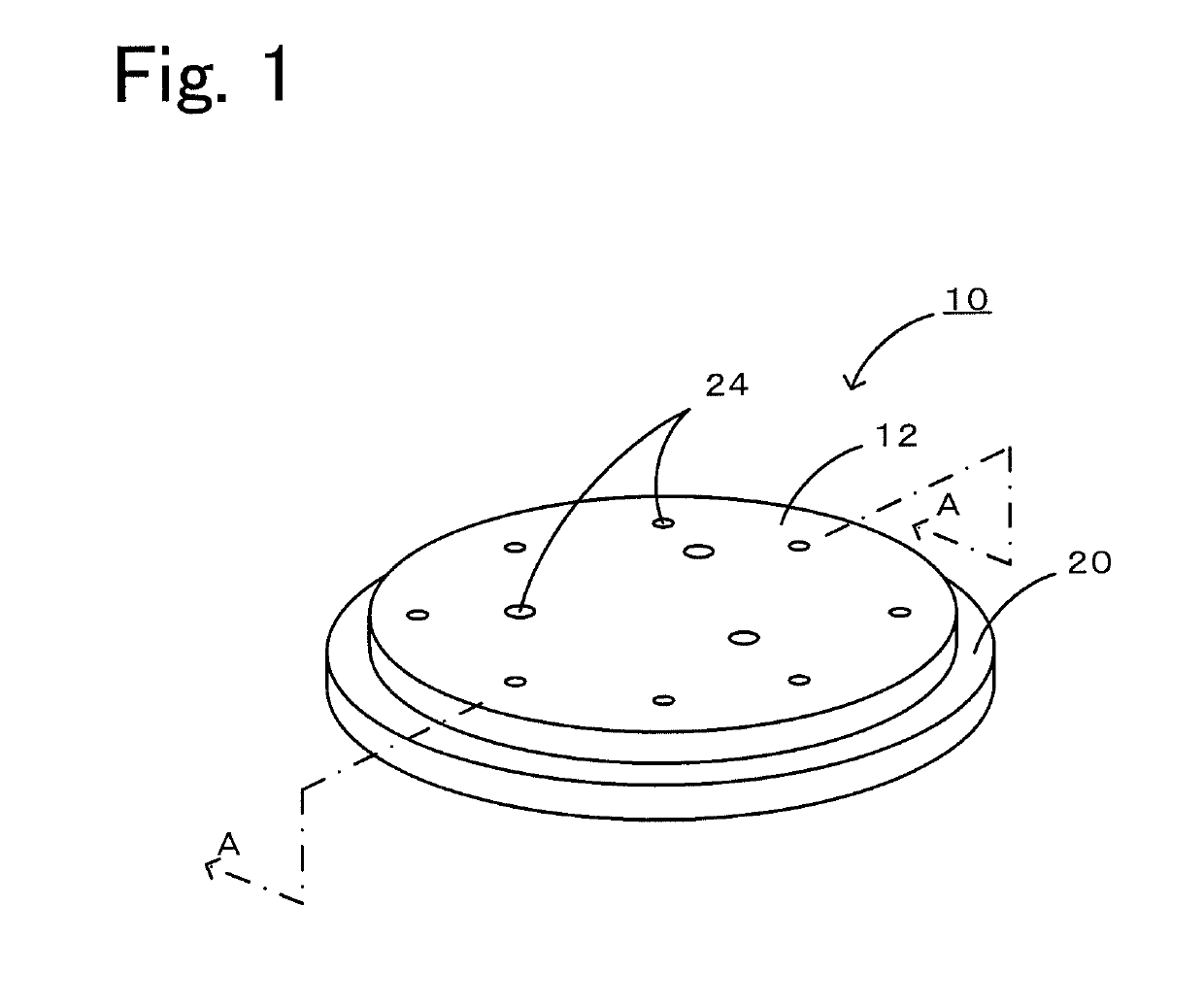
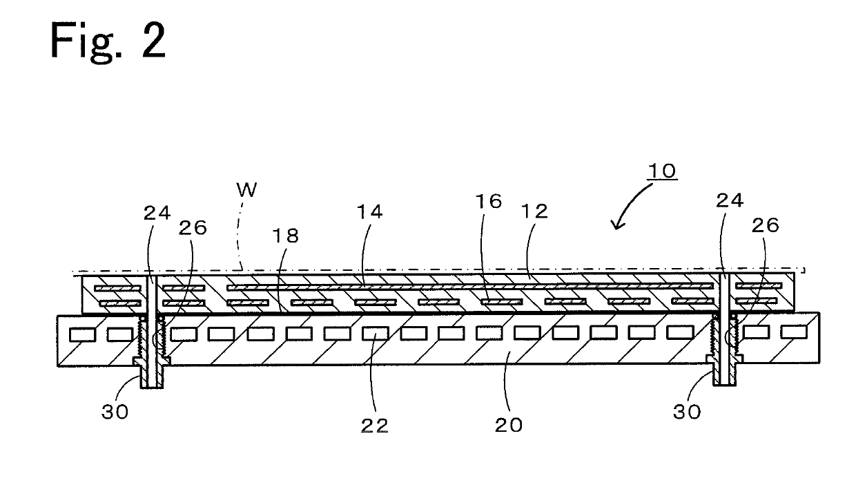
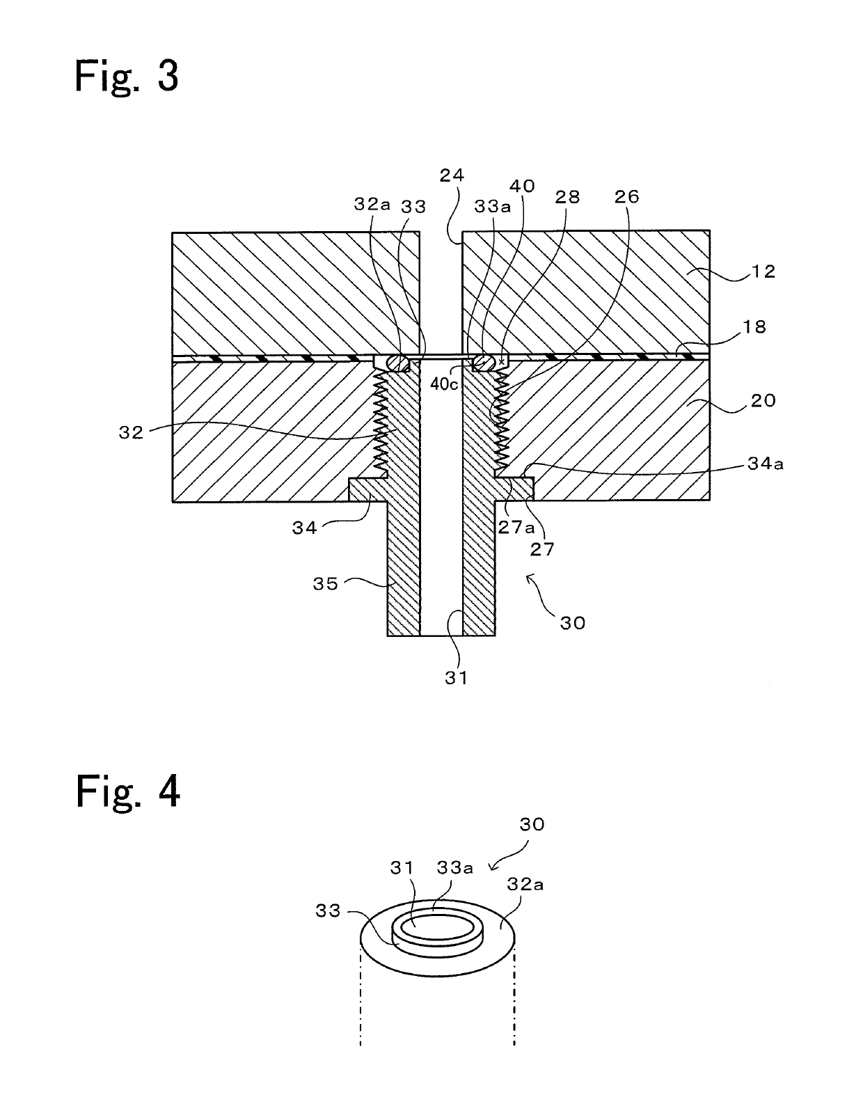
[0032]An embodiment of the present invention will be described below with reference to the drawings. FIG. 1 is a perspective view of an electrostatic chuck 10 that is one example of a wafer susceptor according to the present invention. FIG. 2 is a sectional view taken along A-A in FIG. 1, FIG. 3 is an enlarged view of a region around an insulation pipe 30 in FIG. 2, FIG. 4 is an enlarged perspective view of an annular projected portion 33, and FIG. 5 is a sectional view illustrating a procedure of attaching the insulation pipe 30 into a screw hole 26. It is to be noted that an electrostatic electrode 14, a resistance heating element 16, and a coolant path 22 are omitted in FIGS. 3 and 5.

[0033]The electrostatic chuck 10 includes a plate 12, a cooling board 20, a plurality of through-holes 24, and insulation pipes 30 (see FIGS. 2 and 3) that are inserted into the through-holes 24 and fixed there, respectively. An upper surface of the plate 12 serves as a surface on which a wafer W is ...


PUM


Abstract

A wafer susceptor includes a conductive member attached to a surface of a plate, a through-hole penetrating through the plate and the conductive member, a screw hole formed in a conductive-member penetrating portion of the through-hole, a stopper surface formed in the conductive member, an insulation pipe screwed into the screw hole, and an insulating sealing member arranged between a plate-facing surface of the insulation pipe and the plate, wherein, with a contact surface of the insulation pipe coming into contact with the stopper surface of the conductive member, the insulation pipe is prevented from further advancing into the screw hole, a fore end surface of a sealing-member support portion of the insulation pipe is positioned at a predetermined position where the fore end surface does not contact the plate, and the sealing member is pressed between the plate-facing surface of the insulation pipe and the plate.

Description

BACKGROUND OF THE INVENTION1. Field of the Invention[0001]The present invention relates to a wafer susceptor for use in a semiconductor manufacturing apparatus.2. Description of the Related Art[0002]An electrostatic chuck, a vacuum chuck, etc. are known as wafer susceptors for use in semiconductor manufacturing apparatuses. An electrostatic chuck disclosed in Patent Literature (PTL) 1, for example, has a structure that a ceramic-made plate in which an electrode for generating electrostatic attraction force is embedded is bonded to a cooling board with a resin layer interposed therebetween, and that a through-hole penetrates through the plate and the cooling board. The through-hole is used to receive a lift pin for raising a wafer placed on the plate, and to supply gas to between a rear surface of the wafer and the plate. An insulation pipe is inserted into a portion (i.e., a cooling-board penetrating portion) of the through-hole, which penetrates through the cooling board. The insul...

Claims


Application Information

Patent Timeline
IPC IPC(8): H01L21/687H01L21/683H01L21/302H01L21/67H01J37/32
CPCH01L21/68714H01L21/6833H01L21/302H01L21/67103H01J37/32431H01L21/67109H01L21/67126H01L21/6831H01L21/6838H01L21/68757H01L21/68785
Inventor KUNO, TATSUYAWATANABE, REO
Owner NGK INSULATORS LTD
Why Eureka
Try Eureka