
Condiment Dispenser IX

Active Publication Date: 2019-05-09
BEN ARIE JEZEKIEL
View PDF7 Cites 0 Cited by
  • Summary
  • Abstract
  • Description
  • Claims
  • Application Information

AI Technical Summary

Benefits of technology

[0022]One structural option is to configure the left wall and the right wall planar, vertical and parallel. This creates a channel with equal width. It is useful to make the sliding and propelling sections with a sliding width which is configured to occupy the whole space between the left wall and the right wall. By this configuration, the condiment is prevented from dropping into the left and right sides of the transferring member.
[0023]Another optional feature of the dispenser, is to construct a bottom wall which includes a channel that is configured to accept a pin which is screwed at the propelling lower surface. The pin is configured to travel in the channel along with the propelling section. The pin

Problems solved by technology

This prevalent approach does not prevent natural accumulation of moisture in hygroscopic condiments, which causes excessive condiment coagulation and aperture blockage by moist and sticky con

Method used


Image

  • Condiment Dispenser IX
  • Condiment Dispenser IX
  • Condiment Dispenser IX

Examples


Example

DETAILED DESCRIPTION OF THE DRAWINGS

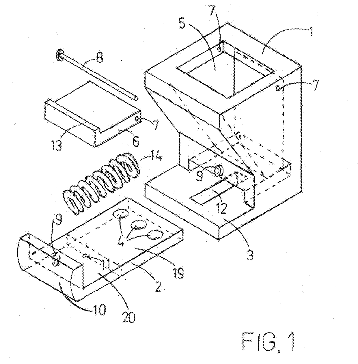
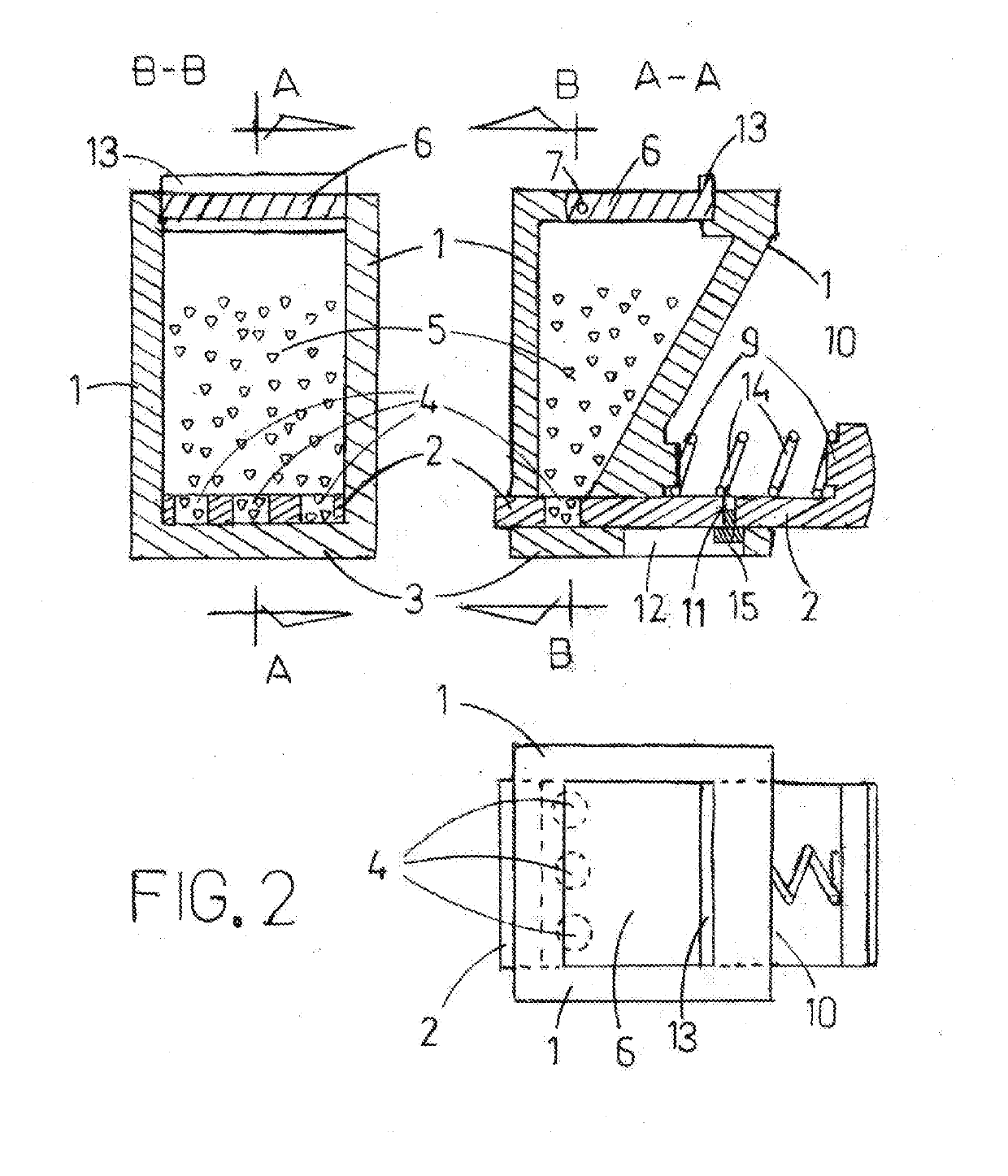
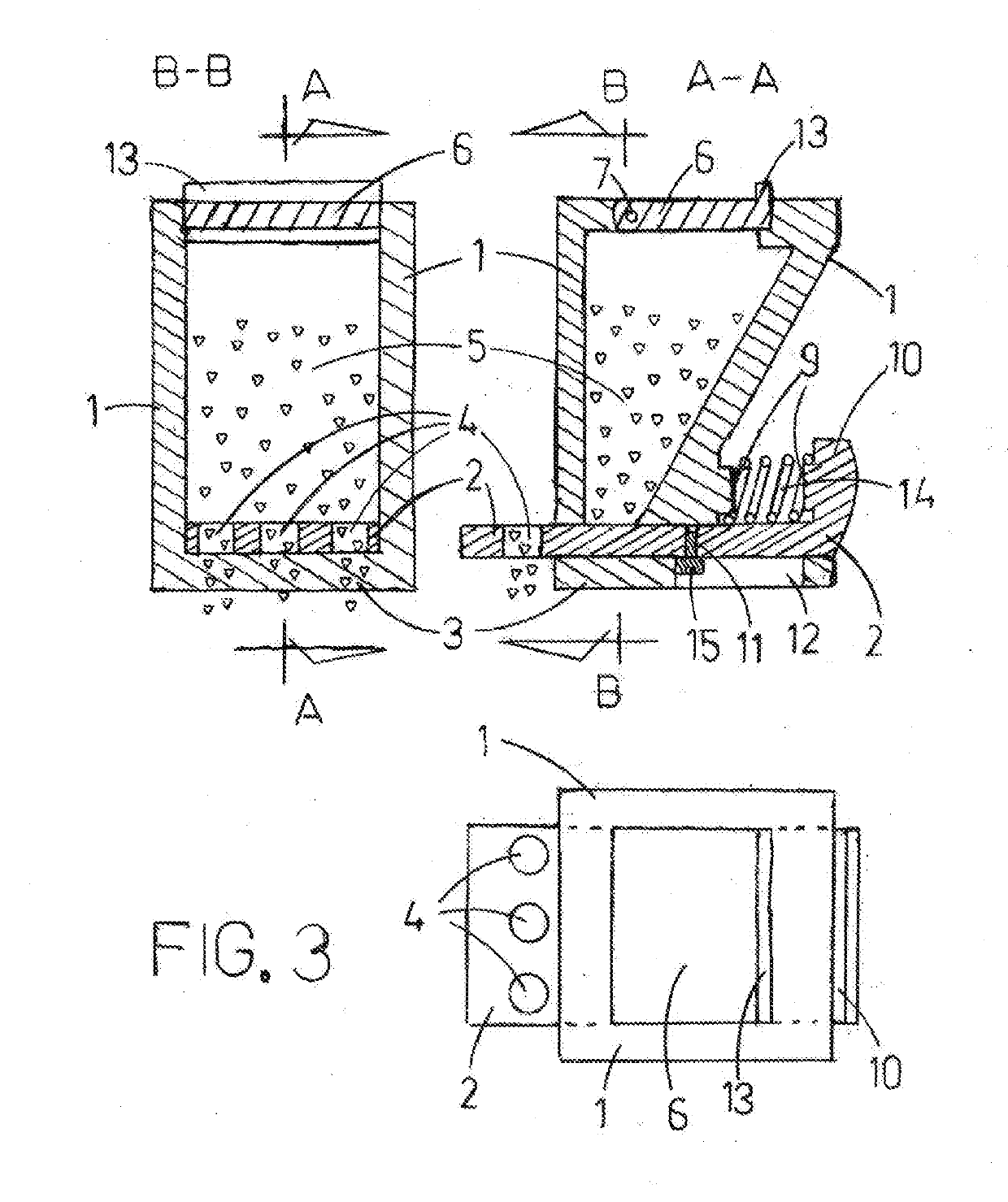
[0032]FIG. 1 illustrates a blow up isometric drawing of an embodiment of a manual condiment dispenser. The condiment dispenser 1 has a bottom wall 3 with a channel 12 which is configured to limit the travel of the transferring member 2 to maximal forwards and backwards positions. The transferring member 2 is divided into a sliding section 19 and a propelling section 20 which includes also the pressing button 10 which is used for manual operation. When the user presses on the pressing button 10 the propelling section 20 moves forward (i.e. to the right) and propels the sliding section to move also to the right. The transferring member 2 moves into the condiment container 5 via the propelling opening 24 and exits via the output opening 25. In FIG. 1 the sliding section 19 has 3 cavities 4 which are loaded when they reside in the condiment container 5. The cavities 4 are unloaded when they reside outside i.e. beyond the output opening 25. The compres...


PUM


Abstract

A condiment dispenser with a dispensing mechanism that automatically loosens condiment coagulation in the condiment container. The user can accurately control the amount of condiment sprinkled on the food because the dispenser dispenses substantially constant amount of condiment for each manual activation. In order to isolate the stored condiment and prevent it from accumulating atmospheric moisture, only the dispensed amounts of condiment are exposed by applying a novel dispensing method of loading measured condiment portions inside the storage, transferring them, unloading and spreading them outside. The dispensing mechanism seldom clogs since it employs wide cavities for measurement, transferring, unloading and spreading.
The condiment dispenser has a simple structure which is inexpensive to manufacture. It can be held and operated using just one hand and it dispenses the condiment directly downwards without needing to downturn the dispenser. The dispenser also has an electrically motorized version.

Description

CROSS-REFERENCE TO RELATED APPLICATIONS[0001]This Application claims priority from a Provisional Patent Application: Ser. No. 62 / 583,519 filed on Nov. 11, 2017FEDERALLY SPONSORED RESEARCH[0002]Not Applicable.SEQUENCE LISTING OR PROGRAM[0003]Not Applicable.TECHNICAL FIELD[0004]The present invention relates to condiment dispensers.PRIOR ART[0005]Many devices were invented for dispensing particulate condiments such as salt and pepper. However the operation of a large majority of them is based on shaking the container and ejecting the condiment particulates via a set of small apertures. The purpose of shaking is to accelerate the particulates in the container forwards and backwards. The forwards acceleration is converted into inertial forces forwards when the container is abruptly accelerated in the reverse direction. These inertial forces push and eject the particulates through a set of apertures whence due to gravity they fall on the food below.[0006]However, condiments and especially...

Claims


Application Information

Patent Timeline
IPC IPC(8): A47G19/18
CPCA47G19/183A47G19/24A47G2200/06A47G19/34
Inventor BEN-ARIE, JEZEKIEL
Owner BEN ARIE JEZEKIEL
Learn More