Component holdback system

Inactive Publication Date: 2013-02-07
PHOENIX CLOSURES
View PDF11 Cites 0 Cited by
  • Summary
  • Abstract
  • Description
  • Claims
  • Application Information

AI Technical Summary

Benefits of technology

The patent is about a mechanism for processing components. The mechanism is designed to hold back components in a way that allows them to be fed into a system easily. This mechanism uses levers to hold back components in a radial manner, so that components in the center of the system are held further back than components in the outer edges. This design takes into account the natural curvature of the system and ensures that components are loaded efficiently. The technical effect of this mechanism is to improve the feeding of components into a system and to ensure that they are processed correctly.

Problems solved by technology

In both cases, the consistent and continuous in-feed of components from one or multiple lines into such mechanisms can be of high importance, as each failed insertion of a component may results in a drop in efficiency.
In may cases, a broken part may be the result of improper insertion.
When feeding components into such a star wheel or a straight pocket, problems may arise.
In some situations, components in the in-feed streams can crowd together and become stuck such that fewer than desired (or no) components are received by the star wheel or straight pocket.
Additionally, as components are generally fed into straight pockets or into star wheels as the star wheels rotate, timing issues may hinder the proper in-feed of components.
Attempting to feed a component into a component receiving mechanism too quickly or too slowly will result in a mis-feed, preventing the component from being received properly.
Additionally, specifically with star wheels, when attempting to feed components into the recesses of a star wheel from multiple in-feed lanes, the natural curvature of the star wheel can create loading issues.

Method used


Image

  • Component holdback system
  • Component holdback system
  • Component holdback system

Examples


Embodiment Construction

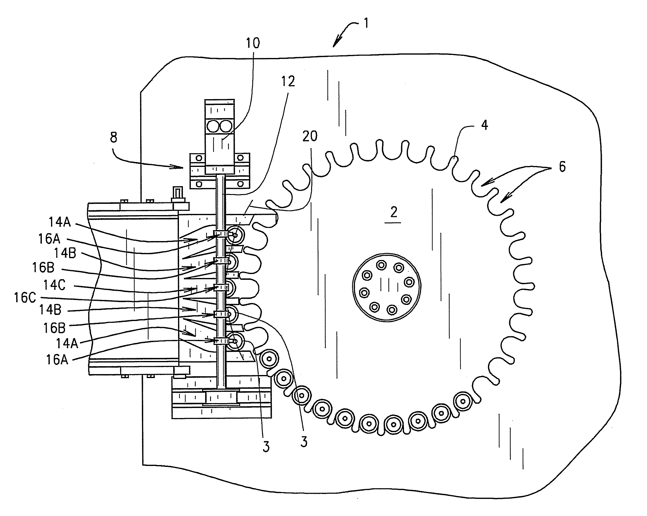
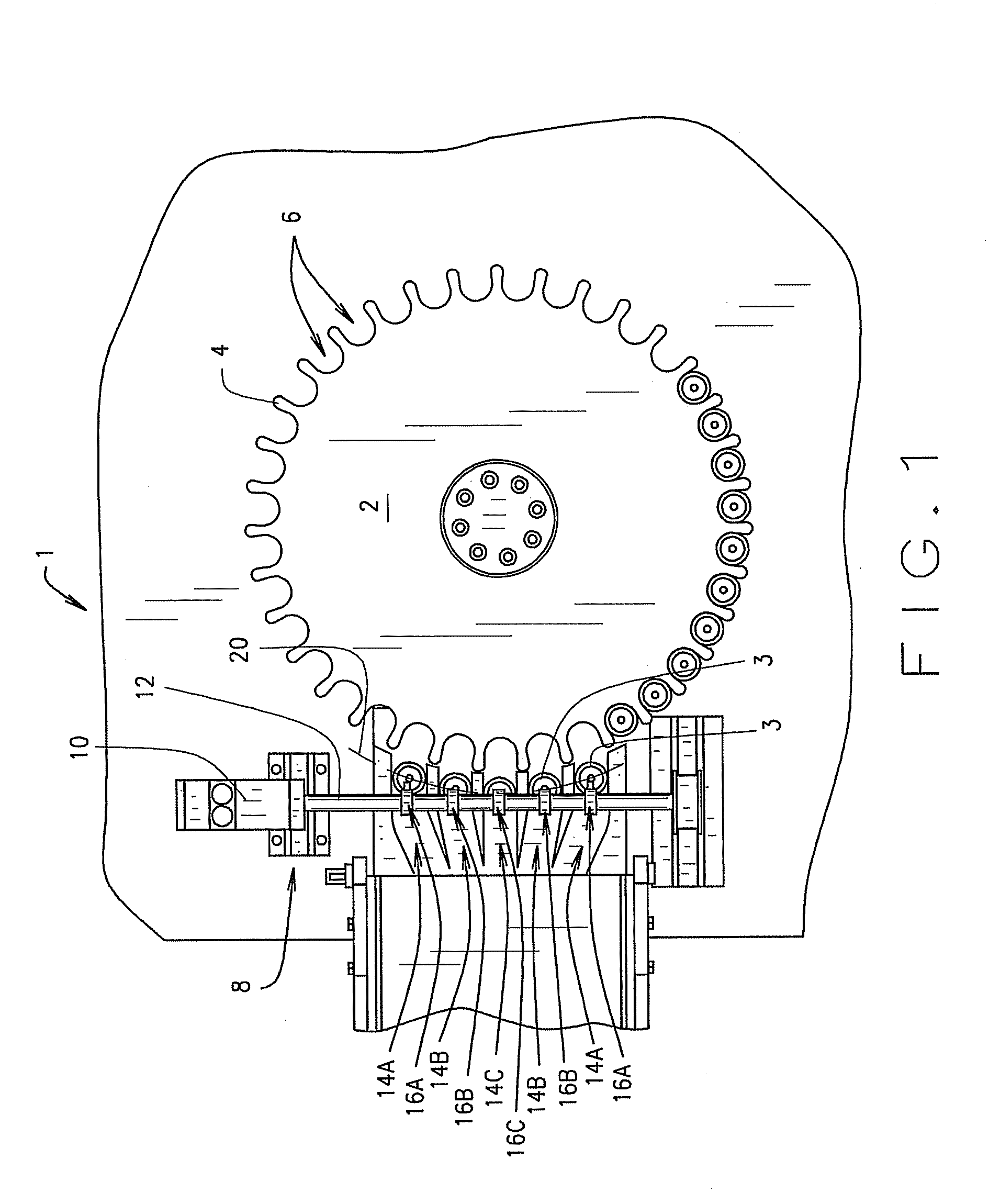
[0021]FIG. 1 illustrates a holdback system 1 according to an embodiment of the present invention. It should be understood that the drawings illustrate a holdback assembly 8 in use with a star wheel 2. However, as discussed above, the holdback assembly 8 may be used in connection with straight pockets or any other component receiving mechanism. The holdback assembly 8 would function essentially identically when used with a different component receiving mechanism.

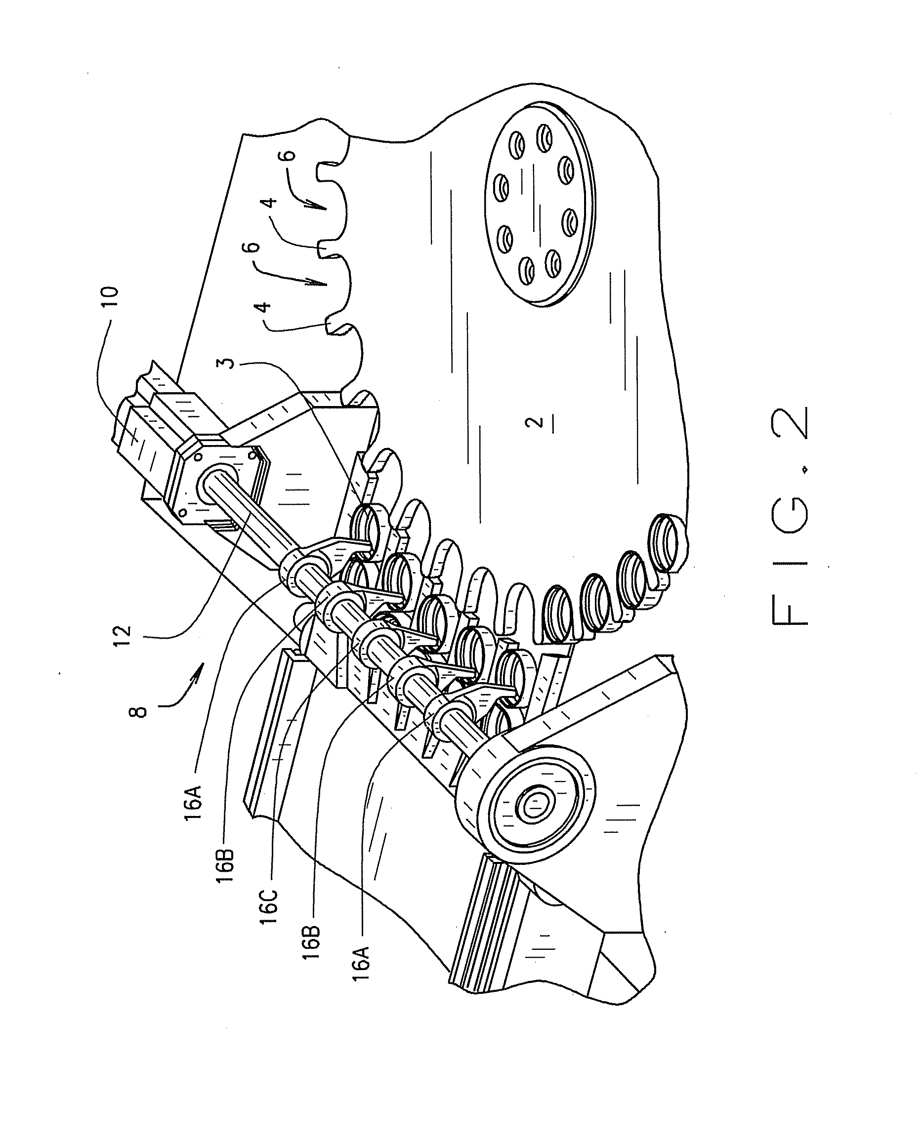
[0022]Star wheel 2 includes cogs 4 and recesses 6, each pair of adjacent cogs 4 defining a recess 6. Each recess 6 of star wheel 2 are sized and shaped to receive a cap 3 therein. Holdback assembly 8 includes a motor 10, a rotatable member 12 and a set of levers 16. Each lever 16 is positioned to be rotatable into and out of a single lane 14. In FIG. 1, five such lanes 14 and levers 16 are shown, with one lever 16 rotatable into each lane 14. However, it is noted that a single lane 14 and lever 16 or any suitable number of la...


PUM


Abstract

A system with rotatable levers spaced and positioned to alternately retain or release components from a plurality of lanes simultaneously into slots of a component receiving mechanism. The levers may be differently sized and shaped to hold back certain components at different positions than others, or the levers may be attached to a rotatable member at varying angles to one another to accomplish such varying holdback patterns. Alternatively, a cam and pin arrangement may be utilized.

Description

BACKGROUND OF INVENTION[0001]The present invention is directed generally to a component holdback system, and more particularly to a system with at least one rotatable or fixed in-line lever positioned to alternately retain or release components from at least one lane of such components while an operation is performed ahead of the holdback point.[0002]Various techniques have been utilized to manage the movement and positioning of components in assembly lines. It is generally well known in the art to single line or multi-line feed lanes which feed components into various mechanisms, such as straight pockets or star wheels (or “sprockets” or “gears” or “dials”) or other suitable component receiving mechanisms. Star wheels, straight pockets and other component receiving mechanisms are often used in assembly line systems to quickly transport components from one workstation to another, or to reduce a number of component in-feed streams down to a single component outflow stream. Star wheel...

Claims


Application Information

Patent Timeline
IPC IPC(8): B65G47/12B65G29/00
CPCB65G47/681B65G47/8823B65G47/846
Inventor ANDERSON, DAVIDEKKERT, LEN
Owner PHOENIX CLOSURES
Why Eureka
Try Eureka