Method and stimulation sleeve for well completion in a subterranean wellbore

a technology of stimulation sleeve and wellbore, which is applied in the direction of fluid removal, borehole/well accessories, construction, etc., can solve the problem of significant risk to the operation

Active Publication Date: 2019-05-09
SUPERSTAGE AS
View PDF7 Cites 15 Cited by
  • Summary
  • Abstract
  • Description
  • Claims
  • Application Information

AI Technical Summary

Benefits of technology

[0028]A second obturator can be landed in a second obturator seat, said second obturator seat being located upstream of t...

Problems solved by technology

The sliding sleeves begin in a closed position, where the ports are isolated and do not allow a fluid path between the wellbore and the formation.
A third well design utilizes coiled tubing-operated sliding sleeves and elimin...

Method used


Image

  • Method and stimulation sleeve for well completion in a subterranean wellbore
  • Method and stimulation sleeve for well completion in a subterranean wellbore
  • Method and stimulation sleeve for well completion in a subterranean wellbore

Examples


first embodiment

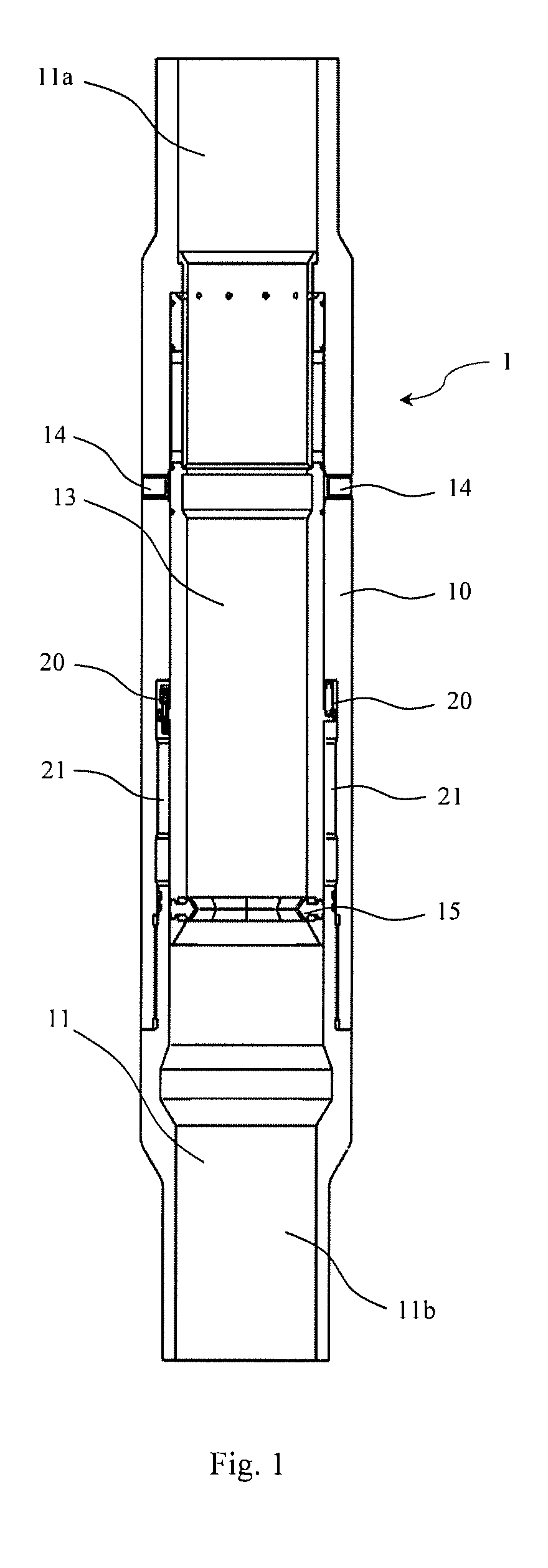
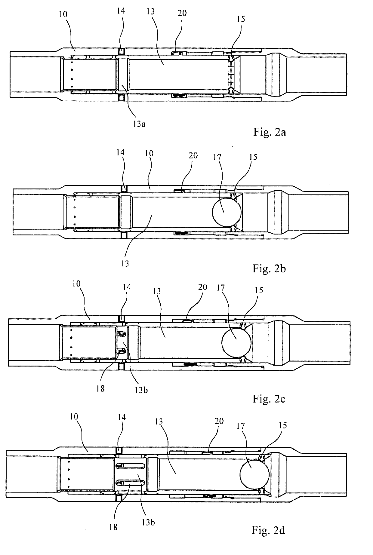
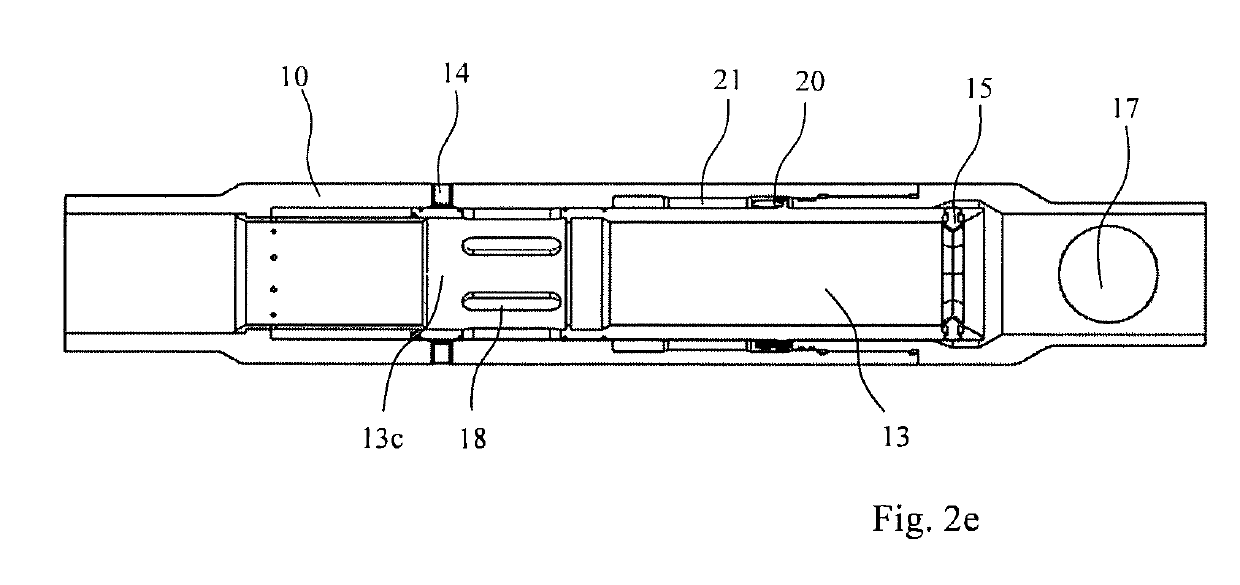
[0061]The inner sliding sleeve 13 of the invention shown in FIGS. 1 and 2a-2e comprises an upper section with three distinct surfaces 13a-13c that can be located across the housing flow ports 14, depending on the sliding sleeve 13 positions. The lower surface 13a is solid, the middle surface 13b has machined holes in the form of for instance longitudinal slits 18, and the upper surface 13c is solid. When the tool is conveyed into the well, the inner sliding sleeve 13 is in its uppermost first position and the solid surface 13a blocks the housing flow ports 14, preventing flow through them. If the sleeve 13 moves down into a second position, the middle surface 13b can be aligned with the flow ports 14, and the longitudinal slits 18 in the sleeve 13 allows flow from the wellbore 34 through the flow ports 14 and into the formation. If the sleeve 13 moves down further past the second position, the upper surface 13c is then aligned with the flow ports 14 in a third position and contains ...

second embodiment

[0073]FIGS. 3 and 4a-4h shows the invention. The alternative configuration of the invention comprises a second landing profile in the form of a second obturator seat 15 which remains retracted in the first and second positions, but is then extended in the third position. The second obturator seat 15 can be used to shift the sliding sleeve 13 to a fourth open position by deploying a second obturator 17 into the well stream 48 of the wellbore 34 and pumping it through all the stimulation sleeves 1. In this configuration, it is desirable to prevent fluid leak off through the fourth position production ports 19 until all stimulation sleeves 1 have been shifted to the fourth position. This can be accomplished by using dissolvable material for plugs that are installed into the fourth position production ports 19 as a temporary barrier.

[0074]Another way to prevent leak off is to use dual action type plug design which are removed hydraulically from the fourth position production ports 19 by...


PUM


Abstract

Stimulation sleeve (1) for well intervention in a subterranean wellbore, comprising: a housing (10) having a through channel (11) with a first end (11a) and a second end (11b), and one or more flow ports (14), and a sliding sleeve (13) disposed axially movable within the housing (10) to open or close said flow ports (14). Said sliding sleeve (13) is equipped with at least a first obturator seat (15) for receipt of a obturator (17) to partially or fully close fluid communication in the through channel (11) of the housing (10), and a time delay mechanism (20) to allow the sliding sleeve (13) to axially travel in the housing (10) at a predetermined speed to open or close said flow ports (14). The invention also discloses a method for well completion in a subterranean wellbore using a sliding sleeve (1).

Description

FIELD OF THE INVENTION[0001]The present invention relates to a method and a stimulation sleeve for well completions in a subterranean wellbore. The stimulation sleeve comprises a housing having a through channel with a first end and a second end, and one or more flow ports, and a sliding sleeve disposed axially movable within the housing to open or close said flow ports, wherein said sliding sleeve is equipped with at least a first seat for receipt of an obturator to partially or fully close fluid communication in the through channel of the housing.[0002]The present invention relates to the field of construction of wells that access subterranean hydrocarbon-bearing formations, where the productivity of such wells is improved by hydraulic stimulation of multiple sections of the wellbore.[0003]The hydraulic stimulation treatment may for instance take the form of hydraulic fracturing, where stimulation fluids are directed from the wellbore to the formation above the formation fracture ...

Claims


Application Information

Patent Timeline
IPC IPC(8): E21B34/10E21B34/06
CPCE21B34/108E21B2034/007E21B34/063E21B43/14E21B43/26E21B2200/06E21B2200/04E21B34/142
Inventor KENT, ANTHONY
Owner SUPERSTAGE AS
Why Eureka
Try Eureka