Brake system and method for braking a motor vehicle

a technology for brake systems and motor vehicles, applied in the direction of brake systems, etc., can solve the problem of no longer being able to access

Active Publication Date: 2021-01-14
ROBERT BOSCH GMBH
View PDF11 Cites 3 Cited by
  • Summary
  • Abstract
  • Description
  • Claims
  • Application Information

AI Technical Summary

Benefits of technology

[0015]According to one preferred embodiment of the brake system according to the present invention, the first hydraulic brake device includes an hydraulic fallback level, which makes it possible for a driver of the motor vehicle to build up brake pressure even without support.

Problems solved by technology

While the second control unit may no longer be able to access the data acquired by the first control unit because the communications link has been severed, it is still able to carry out the braking operation on the basis of the data it received itself.

Method used


Image

  • Brake system and method for braking a motor vehicle
  • Brake system and method for braking a motor vehicle
  • Brake system and method for braking a motor vehicle

Examples


Embodiment Construction

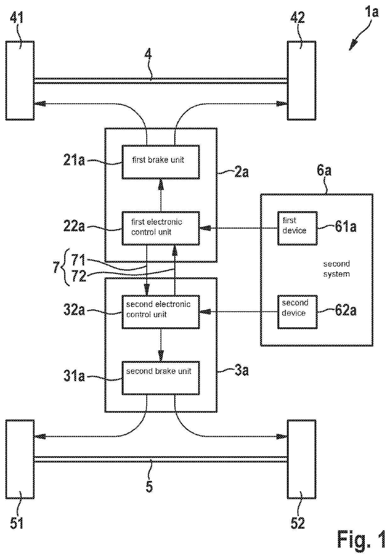
[0030]FIG. 1 shows a schematic block diagram of a brake system 1a having a first hydraulic brake device 2a, which brakes wheels 41, 42 on a first axle 4, in particular a front axle of the motor vehicle. In addition, brake system 1a includes a second hydraulic brake device 3a, which brakes wheels 51, 52 on a second axle 5, in particular on a rear axle of the motor vehicle. For this purpose, first hydraulic brake device 2a includes a first brake unit 21a, which is controlled by a first electronic control unit 22a (ECU) and has hydraulic components in order to decelerate wheels 41, 42 on first axle 4. Accordingly, second hydraulic brake device 3a includes a second brake unit 31a, which is controlled by a second control unit 32a (ECU; electronic control unit) and has hydraulic components in order to decelerate wheels 51, 52 on second axle 5.

[0031]First control unit 22a is electronically coupled with a first device 61a of a sensor system 6a of the motor vehicle, and second control unit 3...


PUM


Abstract

A brake system for a motor vehicle, having a first hydraulic brake device configured to brake wheels on a first axle of the motor vehicle, a first control unit configured to control the braking operation of the wheels on the first axle; and a second hydraulic brake device configured to brake the wheels on a second axle of the motor vehicle, and a second control unit configured to control the braking operation of the wheels on the second axle. The first control unit is coupled with the second control unit via a communication channel. The first control unit and the second control unit are each configured to receive data that are relevant for the control of the braking operation, the first control unit furthermore being configured to transmit a data signal on the basis of the received data via the communication channel to the second control unit.

Description

CROSS REFERENCE[0001]The present application claims the benefit under 35 U.S.C. § 119 of German Patent Application No. DE 102019210271.9 filed on Jul. 11, 2019, which is expressly incorporated herein by reference in its entirety.FIELD[0002]The present invention relates to a brake system for braking a motor vehicle and to a method for braking a motor vehicle.BACKGROUND INFORMATION[0003]Motor vehicles having dual circuit-type braking systems have two mutually independent line circuits for actuating the brakes of the individual wheels. Even if one of the line circuits fails, this allows for a controlled deceleration of the motor vehicle using the remaining line circuit. The two line circuits share a common master brake cylinder. There are basically five different systems with regard to the actuation of the wheels of the different axles, i.e. a II-split, an X-split, an LL-split, an HT-split, and an HH split. The line circuits in different systems differ in the number and placement of th...

Claims


Application Information

Patent Timeline
Patent Type & Authority Applications(United States)
IPC IPC(8): B60T8/26B60T8/32B60T8/36B60T8/40B60T8/48B60T8/94
CPCB60T8/266B60T8/322B60T8/3635B60T8/364B60T13/12B60T8/4022B60T8/4081B60T8/4809B60T8/94B60T8/367B60T8/58B60T8/26B60T13/662B60T13/686
Inventor MAHNKOPF, DIRKMEHL, VOLKER
Owner ROBERT BOSCH GMBH
Why Eureka
Try Eureka