Wave-powered generator

Active Publication Date: 2021-11-18
KHAN GHAZI
View PDF2 Cites 0 Cited by
  • Summary
  • Abstract
  • Description
  • Claims
  • Application Information

AI Technical Summary

Benefits of technology

[0030]It should thus be noted that the prior art focused the harness of sea wave energy in the raising cycle only using the same volume of air that originally was trapped in their respective devices, resulting in major reduction of pressure due to the same volume distributing pressure evenly in all directions diminishing the pressure based on the size of the exit hole. For example, a 5-ton thrust force by sea wave may generate less than 25) pounds per square inch (psi) based at the exit point where the turbine is set to work. The present invention can transfer the same 5 ton thrust through a shaft to the piston with a smaller diameter to compress air resulting in tremendous buildup pressure inside the pump which is useful energy when accumulated with multiple bi-directional pumps using both wave energy as well as kinetic energy using the second half of the wave curve produced by gravity.
[0031]The issue of air pressure caused by the wave must be substantial enough to open the exit valves in a pump. In the present device, this issue has been solved by designing to extract low pressure air, e.g. 50 psi, and stored in air holding tanks and then boosted by air powered boosters to compress its own air volume up to the required pressure. The air volume, usually measured in standard cubic feet per minute (scfm) is increased by using larger pumps for greater production of compressed air which is again doubled by using bidirectional pump wherein both sides of the energy of the full wave curve is extracted by the water buoyancy as well as the weight of the floating structure to exert its own weight to push the piston down by using kinetic energy caused by the wave to complete its cycle.
[0032]In preferred embodiments, the present invention will not solely use water as a working medium. Instead, the present invention uses air as a working medium for air pumping which is compressible by using the up and down as well as unidirectional column pressure to extract the maximum wave energy force in the simplest way possible. This unique process m

Problems solved by technology

It should thus be noted that the prior art focused the harness of sea wave energy in the raising cycle only using the same volume of air that originally was trapped in their respecti

Method used


Image

  • Wave-powered generator
  • Wave-powered generator
  • Wave-powered generator

Examples


Example

[0056]An artisan of ordinary skill need not view, within isolated figure(s), the near infinite number of distinct permutations of features described in the following detailed description to facilitate an understanding of the present invention.

DETAILED DESCRIPTION OF THE INVENTION

[0057]The present disclosure is not to be limited to that described herein. Mechanical, electrical, chemical, procedural, and / or other changes can be made without departing from the spirit and scope of the present invention. No features shown or described are essential to permit basic operation of the present invention unless otherwise indicated.

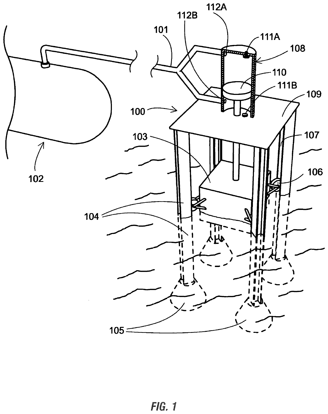
[0058]FIG. 1 shows the vertically mounted wave air compression station 100, which pumps air through a pipe 101 to a compressed air storage tank 102. The station is supported by posts 104, which are preferably anchored via bolts at their feet 105 in the sea floor. Other suitable means of fastening the housing of the air compression station 100 can be used. A float 103...


PUM


Abstract

A machine and process to compress ambient air using natural swell of ocean waves to store energy. The devise is a bi-directional air pump operated by ocean wave power of water buoyancy as well as earth gravity in a pressure vessel using a piston. The machine uses a large surface area as float connected by a rod to a small area as piston, housed in a pressure vessel to multiply compression of air. The compression of air is directly proportional to the respective surface areas of float to the piston attached with a rod inside the pressure vessel. An array of similar machines can be employed to multiply potential energy output.

Description

FIELD OF THE INVENTION[0001]The present invention relates generally to an apparatus and corresponding method of use in at least the renewable energy industry. More particularly, but not exclusively, the present invention relates to a wave-powered generator. As will be understood, any of the aspects disclosed herein may be used to adapt machines or engines which include power stations capable of harvesting tide energy through the relative movement between a wave-operated member, such as a wom, and a reaction member, such as a rem, fixed with respect to the sea bed or shore.BACKGROUND OF THE INVENTION[0002]The background description provided herein gives context for the present disclosure. Work of the presently named inventors, as well as aspects of the description that may not otherwise qualify as prior art at the time of filing, are neither expressly nor impliedly admitted as prior art.[0003]There have been many attempts to find a viable option to harness sea wave energy, none of wh...

Claims


Application Information

Patent Timeline
IPC IPC(8): F04B35/00F03B13/16F03B13/24
CPCF04B35/004F03B13/24F03B13/16Y02E10/30F03B13/187F05B2240/40F05B2240/91F05B2270/342F05B2270/202F05B2260/64
Inventor KHAN, GHAZI
Owner KHAN GHAZI
Why Eureka
Try Eureka