Self contained heating/cooling roof top unit with built in independent pressure relief

a self-contained, pre-fabricated technology, applied in lighting and heating apparatus, ventilation systems, heating types, etc., can solve problems such as damage to the building, security risks, and pressure buildup in the building

Inactive Publication Date: 2011-09-20
2109617 ONTARIO
View PDF6 Cites 4 Cited by
  • Summary
  • Abstract
  • Description
  • Claims
  • Application Information

AI Technical Summary

Benefits of technology

[0007]It is an object of the present invention to provide a one embodiment self-contained pre-manufactured air unit for installation on a roof top of a building where the unit contains a third duct connection point. The third connection point is used for relief air only and is independent of the blower that forces air into the building through a first connection point and independent of the return air duct from the building, which is a second connection point. The third connection point is connected to an exhaust outlet from the unit. The exhaust outlet can have a pressure operated damper thereon that opens to exhaust air using building pressure only and closes when there is no building pressure. The third connection point can lead to a protected enclosure within the unit. The enclosure is preferably located in a condenser area of the unit, which already has one or more passages to exhaust air from the unit to ambient air. The pressure activated damper is preferably located between the enclosure and the condenser area in which the enclosure is located. By relieving air in this manner, the pressure operated damper can operate without the opposing forces caused by the blower in the unit and the damper will be protected from adverse weather conditions. The third connection point can also lead directly to an exhaust vent located on the exterior of the unit.
[0008]It is a further object of the present invention to provide an air unit that is mounted on a roof top of a building to circulate air through the building and back to the unit where the unit has an independent pressure relief opening. It is still a further object of the present invention to provide a method of relieving pressure from a building caused by the operation of a roof top air unit by locating a pressure relief opening that is connected into the building on the unit, the pressure relief opening being independent of the blower.

Problems solved by technology

The units can cause a pressure buildup in the building as buildings are now constructed to be airtight.
The pressure buildup can cause exit doors in the building, some of which are designed to close automatically when someone enters or exits the building, to remain open, thereby creating a security risk.
Further, the pressure buildup can cause damage to the building.
The pressure buildup is often caused by the pressure operated relief damper within the housing not opening properly as the damper is subject to opposing forces caused by operation of the main fan.
The secondary fan often does not work very well to relieve pressure within the building because the secondary fan is opposed by the main fan or blower within the housing.
When the main fan or blower is operating, the damper in the exhaust vent can fail to open satisfactorily or will not operate properly as the secondary fan is pulling in one direction and that the main fan or blower is pulling the damper in the opposite direction.

Method used


Image

  • Self contained heating/cooling roof top unit with built in independent pressure relief
  • Self contained heating/cooling roof top unit with built in independent pressure relief
  • Self contained heating/cooling roof top unit with built in independent pressure relief

Examples


Embodiment Construction

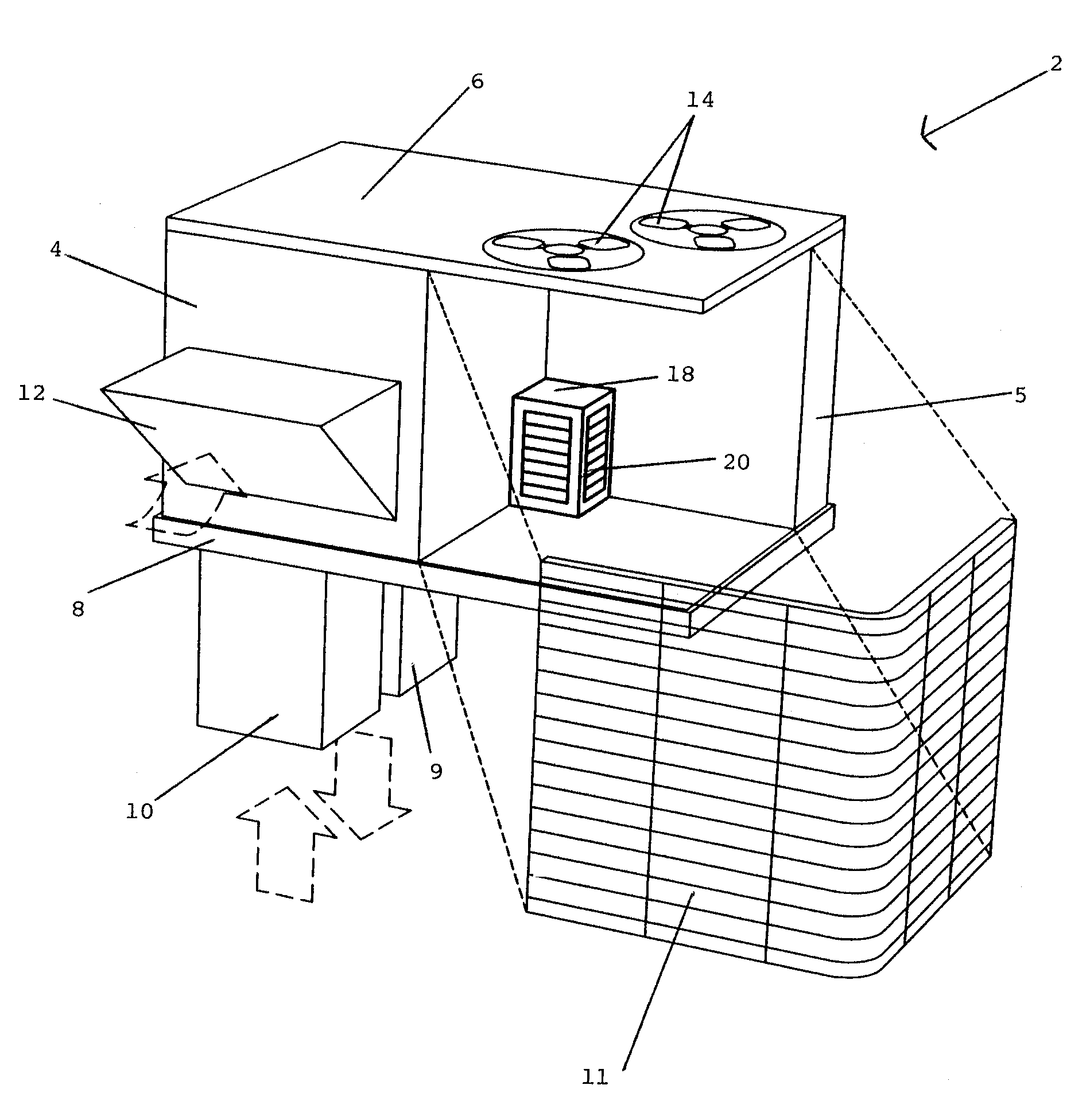
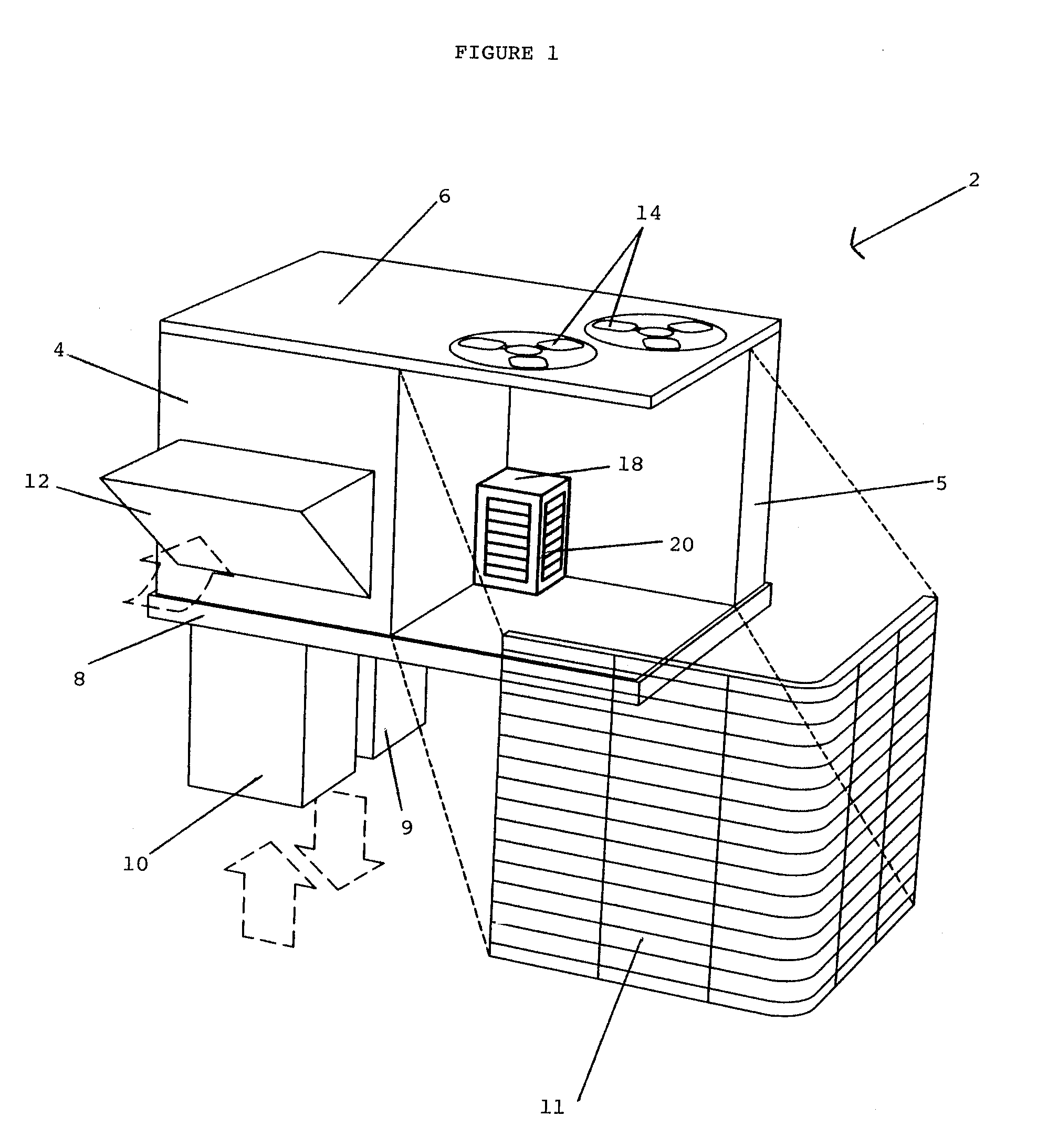
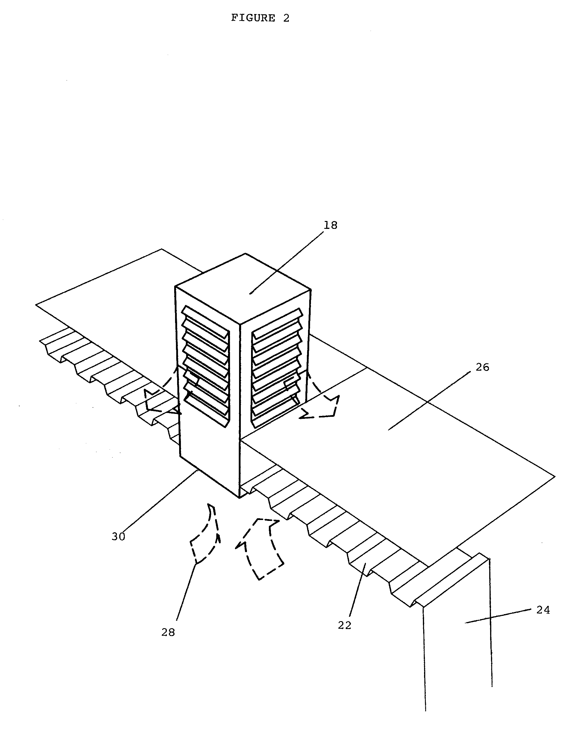
[0024]In FIG. 1, an air unit 2 for mounting on a roof top of a building (not shown in FIG. 1) to heat or cool an interior of the building has a first housing 4 and second housing 5. While the unit can be used solely for air circulation, the unit is preferably used for heating and cooling and contains a condenser coil. The first and second housings 4, 5 have a top 6 and bottom 8 with a blower, condenser coil (all conventional and not shown), air outlet 9 and return air inlet 10 located within the first housing 4. The second housing 5 has a part of the condenser coil 11 extending around two sides thereof. The condenser coil 11 is connected to that part (not shown) of the coil located within the first housing 4. The first housing 4 has a first air inlet 12 to allow ambient air to enter the first housing 4 and to be forced into the building [not shown] by the blower (not shown) through the air outlet 9 located within the first housing 4. The fresh air (i.e. ambient air) is mixed with so...


PUM


Abstract

A self-contained pre-manufactured roof top unit is used to circulate fresh air, heat or cool a building. The housing has a blower connected into a circulation system to circulate air into and out of the building. The unit has a pressure relief opening for connection into the building that is used to relieve air pressure buildup within the building. The pressure relief opening is part of a pressure relief passage that is independent of the blower and has an exhaust vent that opens and closes automatically in response to pressure differential between the building and ambient air.

Description

[0001]Applicant claims the benefit of U.S. Provisional Applications Ser. No. 60 / 772,558 filed on Feb. 13, 2006, Ser. No. 60 / 780,381 filed on Mar. 9, 2006, and Ser. No. 60 / 744,393 filed Apr. 6, 2006.BACKGROUND OF THE INVENTION[0002]1. Field of the Invention[0003]This invention relates to a self-contained pre-manufactured air unit for installation on a roof top of a building. This unit has three connection points for ductwork. One connection point is used to supply air to the building and the second connection point is used to return air from the building through an air circulation system that includes a blower. The third connection point is also part of the unit, but is connected independently of the blower and is used to relieve pressure within the building. The unit may have a heating coil, a cooling coil or a heating / cooling coil and an air inlet for ambient air.[0004]2. Description of the Prior Art[0005]Self-contained pre-manufactured roof top heating / cooling units are known in w...

Claims


Application Information

Patent Timeline
Patent Type & Authority Patents(United States)
IPC IPC(8): F24F7/02
CPCF24F7/025F24F13/1413F24F2011/0042F24F2110/40
Inventor TOLLAR, GREIG J.
Owner 2109617 ONTARIO
Why Eureka
Try Eureka