
Stroking Tool Using at Least One Packer Cup

a tool and packer cup technology, applied in the field of downhole tools, can solve the problems of increasing product cost, preparing the expensive surface of the moving surface that goes past the seal, etc., and achieve the effect of reducing the pressure ahead and building pressur

Active Publication Date: 2010-09-30
BAKER HUGHES INC
View PDF25 Cites 2 Cited by
  • Summary
  • Abstract
  • Description
  • Claims
  • Application Information

AI Technical Summary

Benefits of technology

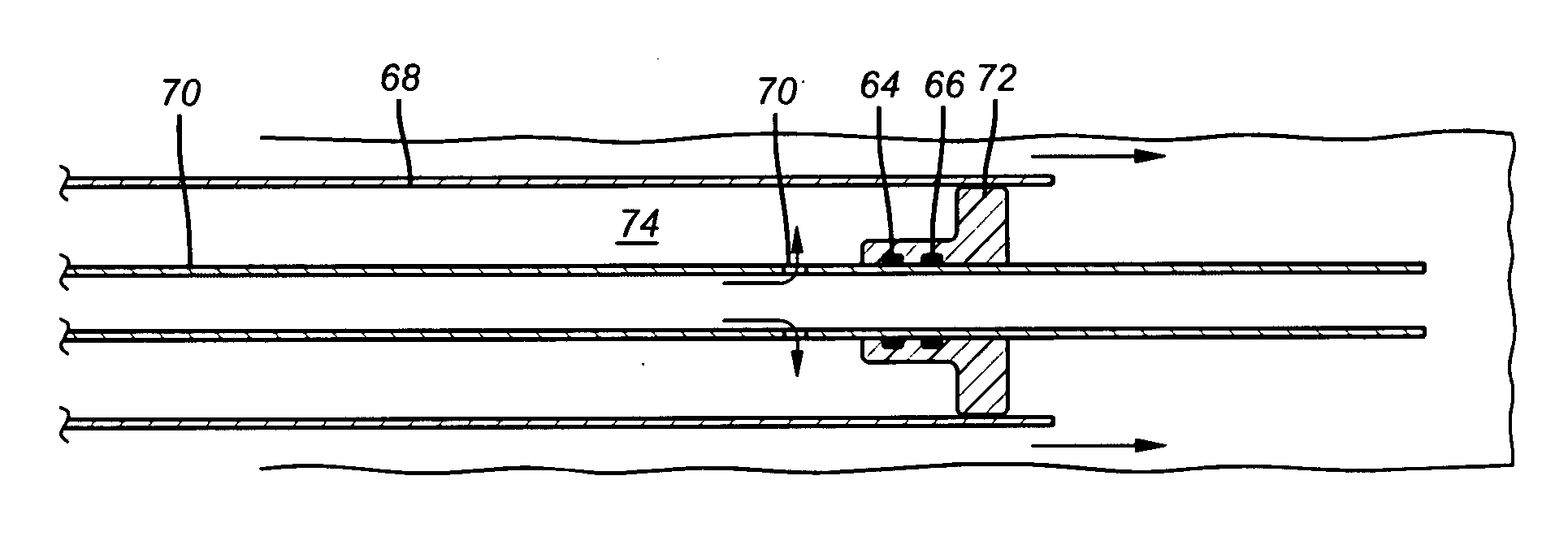
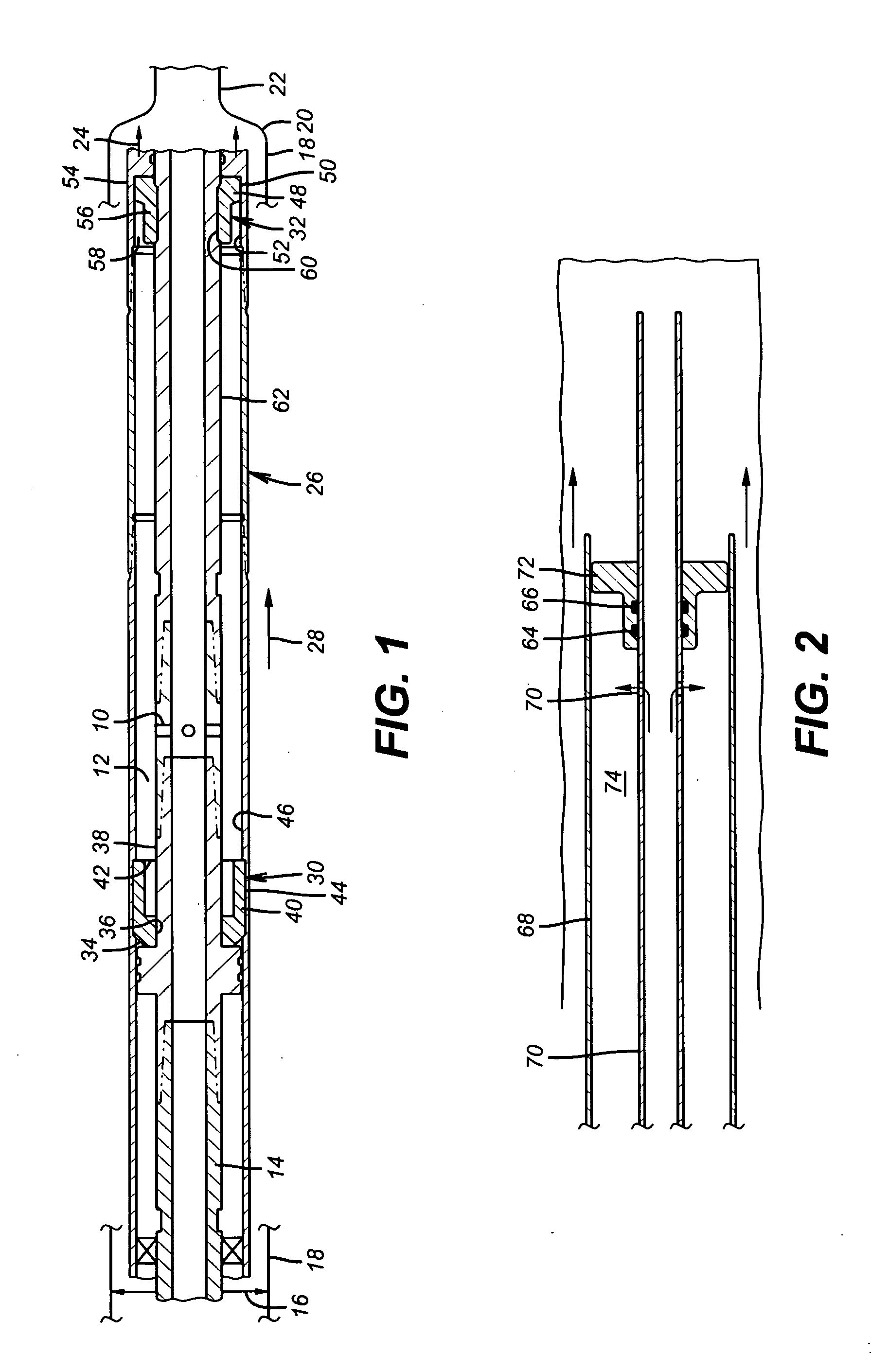
[0007]A tool for subterranean use envisions relative movement between a housing and a piston by pressurizing and removing pressure in a variable volume defined between them. The variable volume is sealed with packer cups preferably with one supported from the piston and the other off the housing and in opposed orientations so that the broad surface area on each packer cup abuts the surface where relative movement takes place. The downhole tasks accomplished with the relative movement can be varied and include tubular expansion, setting packers or shifting sleeves, for example. Alternative embodiments envision use of a single or multiple packer cups tied to a structure that needs to be driven and building pressure behind a packer cup or reducing pressure ahead of it to advance it.

Problems solved by technology

In a subterranean environment the expansion of tubulars frequently requires force applied to a swage that cannot be delivered through the surface equipment.
The problem with sealing with the chevron seal stacks is the expensive surface preparation of the moving surface that goes past the seals.
In some versions the contact surface was chrome plated after an expensive surface cleaning operation to remove burrs and other surface irregularities.
In some instances the piston was a machined part adding to the product cost.

Method used


Image

  • Stroking Tool Using at Least One Packer Cup
  • Stroking Tool Using at Least One Packer Cup

Examples


Embodiment Construction

[0010]FIG. 1 illustrates how the relative movement is generated with applied pressure to ports 10 leading to a variable volume cavity 12. A tubular string 14 has an anchor schematically illustrated by arrow 16 for selective grip on an existing tubular string 18 shown discontinuously at opposed ends of FIG. 1. String 18 has a taper 20 leading to a smaller diameter section 22 to be expanded. Arrows 24 represent a swage secured to a lower end of a piston assembly 26. The piston assembly 26 is movable with respect to string 14 which acts as a stationary mandrel when anchored to the tubular string 18 at anchor 16. In the view of FIG. 1 the assembly 26 has been propelled downhole to the fullest extent with respect to the mandrel 14 that is needed to define the variable volume cavity 12. A travel stop (not shown) can be used to limit the movement of the assembly 26 in the direction of arrow 28 with respect to mandrel 14. After the position of FIG. 1 is reached, the pressure in the mandrel ...


PUM


Abstract

A tool for subterranean use envisions relative movement between a housing and a piston by pressurizing and removing pressure in a variable volume defined between them. The variable volume is sealed with packer cups preferably with one supported from the piston and the other off the housing and in opposed orientations so that the broad surface area on each packer cup abuts the surface where relative movement takes place. The downhole tasks accomplished with the relative movement can be varied and include tubular expansion, setting packers or shifting sleeves, for example. Alternative embodiments envision use of a single or multiple packer cups tied to a structure that needs to be driven and building pressure behind a packer cup or reducing pressure ahead of it to advance it.

Description

FIELD OF THE INVENTION[0001]The field of this invention is downhole tools of the type that extend a piston in response to pressurizing an annular space and more particularly where the space is sealed with a packer cup.BACKGROUND OF THE INVENTION[0002]In a subterranean environment the expansion of tubulars frequently requires force applied to a swage that cannot be delivered through the surface equipment. To accomplish such expansions an assembly of tools has been used that has a swage at the lower end and a resettable anchor at the upper end. In between is a stroking tool. Applying pressure in a string that supports this assembly first sets the anchor and then pressurizes an annular chamber between a housing and a piston that is inside it. The annular space is sealed with end seals between the relatively movable components. The swage is secured to the movable piston. Extension of the piston drives the swage through the tubular. If the expansion is top down, at the end of the piston ...

Claims


Application Information

Patent Timeline
Patent Type & Authority Applications(United States)
IPC IPC(8): E21B33/12
CPCE21B4/18E21B43/105E21B23/04E21B23/0411
Inventor STOREY, BRYAN T.ADAM, MARK K.
Owner BAKER HUGHES INC
Learn More