Arm for turbine-engine casing comprising a removable additional piece

Active Publication Date: 2019-05-09
SN DETUDE & DE CONSTR DE MOTEURS DAVIATION S N E C M A
View PDF0 Cites 2 Cited by
  • Summary
  • Abstract
  • Description
  • Claims
  • Application Information

AI Technical Summary

Benefits of technology

[0009]The aim of the invention is in particular to provide

Problems solved by technology

However, the bearing of the transmission shaft needs regular maintenance operations that require this bearing to be dismantled.
However, removing this bear

Method used


Image

  • Arm for turbine-engine casing comprising a removable additional piece
  • Arm for turbine-engine casing comprising a removable additional piece
  • Arm for turbine-engine casing comprising a removable additional piece

Examples


Embodiment Construction

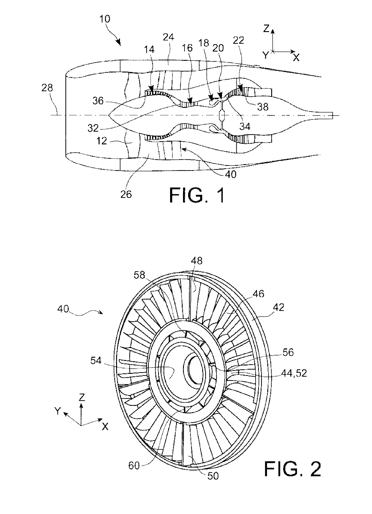
[0069]FIG. 1 illustrates a turbine engine 10 for an aircraft of a known type, for example a twin-spool bypass turbine engine, comprising in general terms a fan 12 intended for aspirating an airflow dividing downstream of the fan into a primary flow supplying a core of the turbine engine and a secondary flow bypassing this core. The core of the turbine engine comprises, in general terms, a low-pressure compressor 14, a high-pressure compressor 16, a combustion chamber 18, a high-pressure turbine 20 and a low-pressure turbine 22. The turbine engine is faired by a nacelle 24 surrounding the secondary flow channel 26. The rotors of the turbine engine are mounted so as to rotate about a longitudinal axis 28 of the turbine engine.

[0070]In the whole of this description, the axial direction X is the direction of the longitudinal axis 28 of the turbine engine, the vertical direction Z is a direction orthogonal to the axial direction X and oriented along the vertical when the turbine engine e...


PUM


Abstract

To facilitate the removal of a bearing housed in an arm of a turbomachine casing, which bearing guides a transmission shaft of the turbomachine, a casing arm includes a body with a vertical portion and a base defining a portion of a shaft housing; an additional part removably attached to the body and defining a bearing housing opening in the shaft housing; and a removable shim inserted between the base and the additional part. A turbomachine including such a casing arm is also described, as well as a method for removing the bearing from such a turbomachine, including removing the shim and moving the additional part towards the base, thereby allowing access to the bearing.

Description

TECHNICAL FIELD[0001]The present invention relates to the field of turbine engines for aircraft, and relates more particularly to a casing arm intended to house a secondary transmission shaft, and a turbine engine comprising such a casing arm.[0002]The invention also relates to a method for removing a bearing intended for guiding a transmission shaft of such a turbine engine.PRIOR ART[0003]In an aircraft turbine engine, a transmission shaft in general connects a rotor shaft of the turbine engine to auxiliary equipment such as a starter of the turbine engine. The rotor shaft is a shaft centred on the axis of the turbine engine and connecting a compressor arranged upstream of a combustion chamber to a turbine arranged downstream of the combustion chamber, in a well known fashion.[0004]The transmission shaft is sometimes composed of a primary transmission shaft and a secondary transmission shaft mounted end to end and coupled to one another at a bearing providing the guidance and centr...

Claims


Application Information

Patent Timeline
IPC IPC(8): F01D25/24F01D25/16F02C7/36F02C7/32F02C7/06
CPCF01D25/24F01D25/162F02C7/36F02C7/32F02C7/06F02K3/06F05D2230/70F05D2260/4031F05D2240/14F01D9/065F01D15/12
Inventor JUIGNE, SEBASTIEN NICOLASCONTAL, KEVIN MICHEL ROBERTGAILLOT, MATHIEUMARLIN, FRANCOIS MARIE PAULNICAISE, STEVE MARCEL
Owner SN DETUDE & DE CONSTR DE MOTEURS DAVIATION S N E C M A
Why Eureka
Try Eureka