Method for setting correct roller bearing clearance

Inactive Publication Date: 2019-05-09
PEERLESS WINSMITH
View PDF0 Cites 4 Cited by
  • Summary
  • Abstract
  • Description
  • Claims
  • Application Information

AI Technical Summary

Benefits of technology

[0008]It is another object of the present invention to provide a method that allows an effective, accurate and efficient setting of a correct clearance of gear reducer tapered roller bearings.
[0009]It is another object of the present invention to provide a method that allows an effective, accurate and efficient setting of a correct clearance of gear reducer tapered roller bearings without disassembling an already assembled gear reducer.
[0010]These and other objects and advantages of the present invention are achieved in the preferred embodiments set forth below by providing a method of setting the clearance of a tapered roller bearing assembly of the type having a housing with an access opening, and in which housing is positioned an input shaft engaging a worm or gears for driving an output gear eng

Problems solved by technology

Improperly adjusted bearings can lead to increased wear, reduced life and excess fr

Method used


Image

  • Method for setting correct roller bearing clearance
  • Method for setting correct roller bearing clearance
  • Method for setting correct roller bearing clearance

Examples


Embodiment Construction

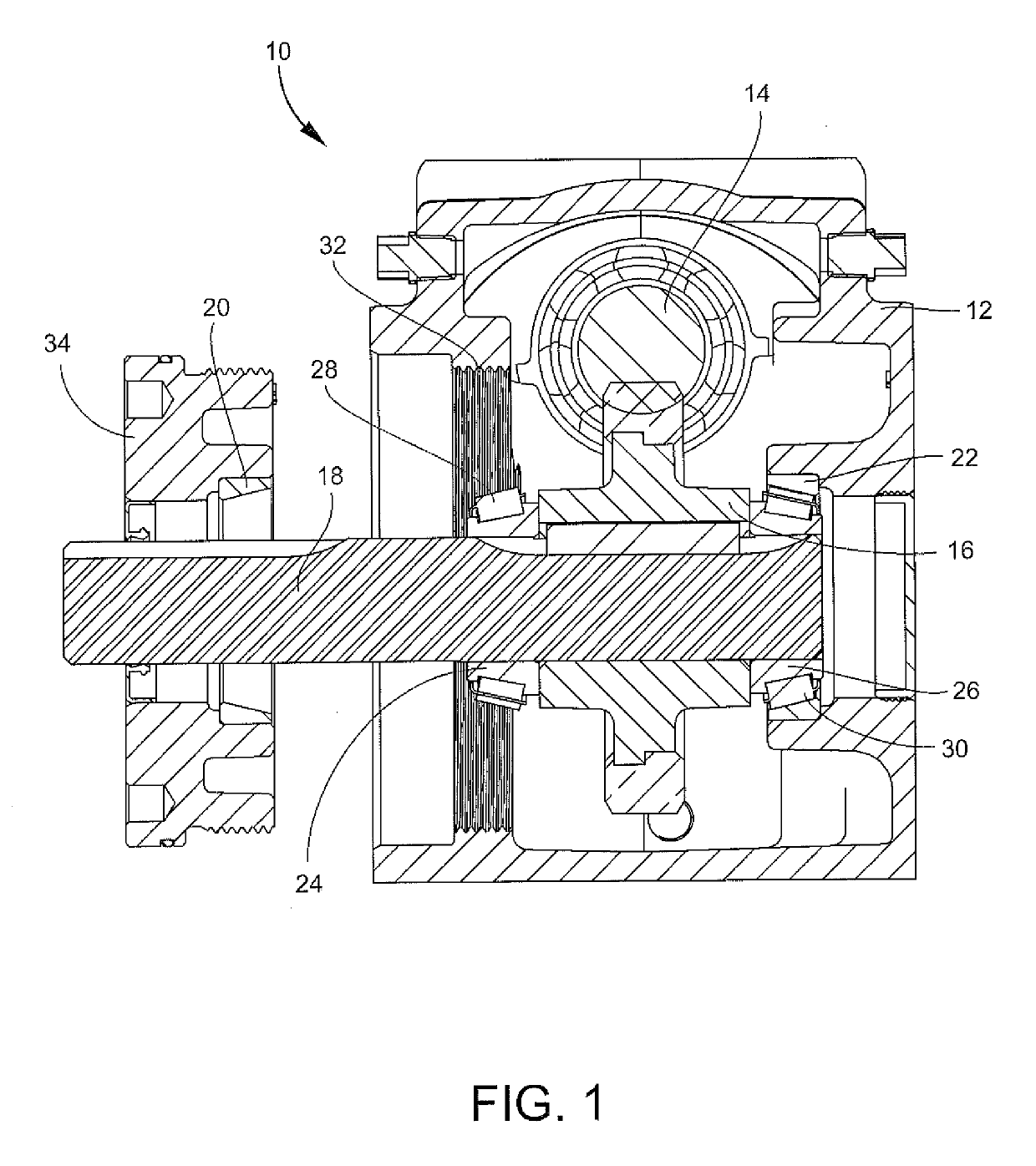
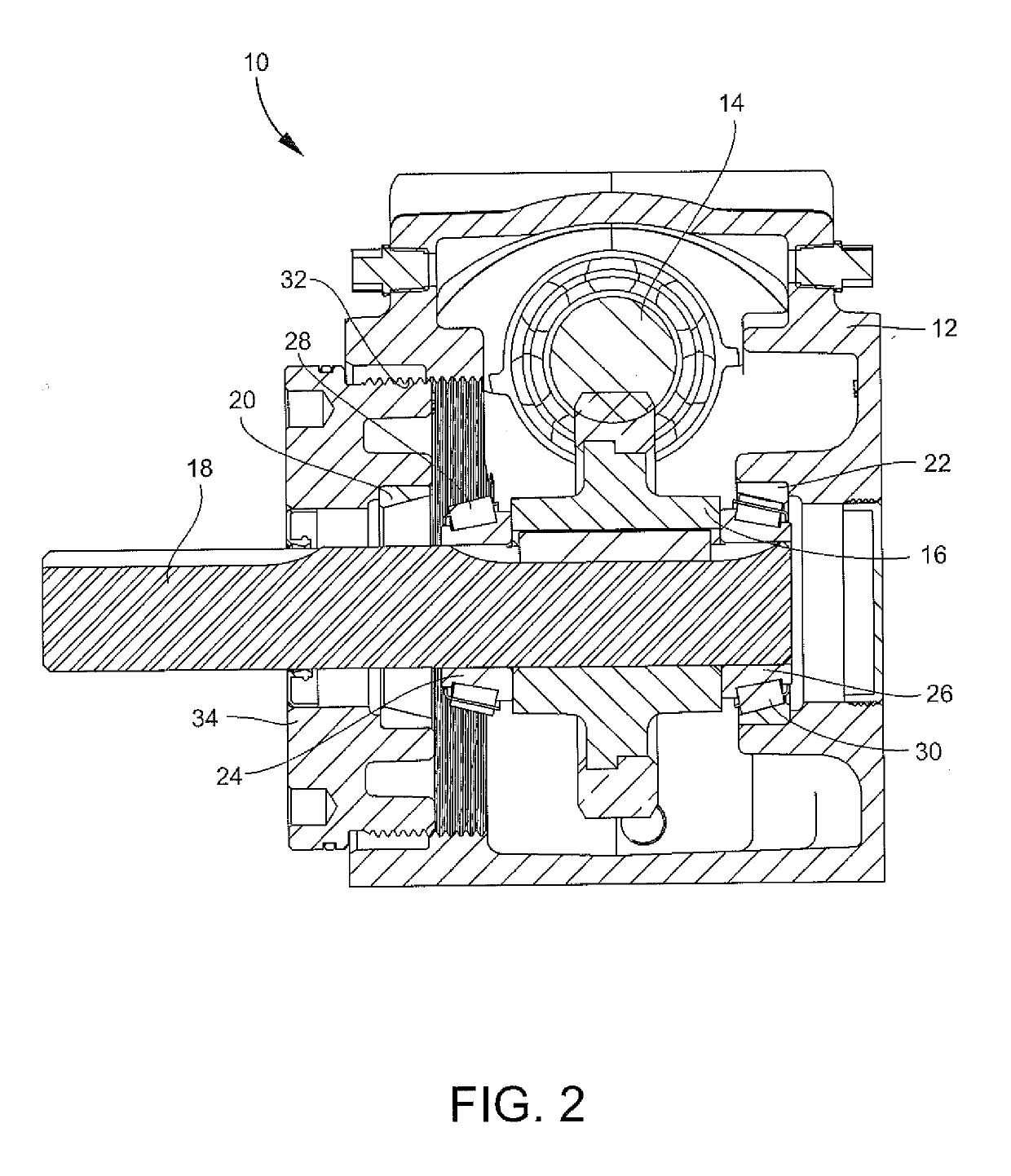
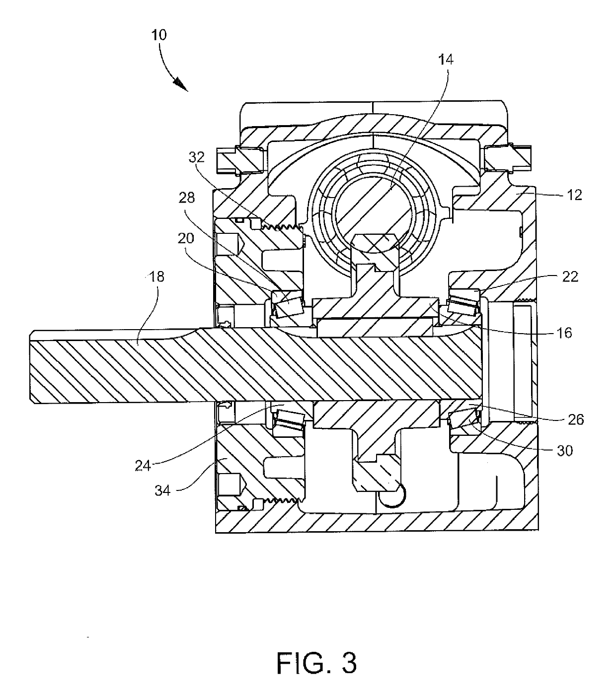
[0024]Referring now to FIGS. 1-4, a gear reducer 10 includes a housing 12 in which is mounted an input gear, such as the shown worm 14 that engages and transfers rotation to an output gear wheel mounted on an output shaft 18. Tapered bearing cups 20, 22 are mounted in a cover 34 and housing 12 surrounding the output shaft 18. Complementary bearing cones 24, 26 are mounted on the output shaft 18, with roller bearings 28, 30 mounted for rotation between the bearing cups 20, 22 and the bearing cones 24, 26. The bearing cups 20, 22, bearing cones 24, 26 and roller bearings 28, 30 collectively form the roller bearing assembly.

[0025]The housing 12 includes a threaded access opening 32 adapted to receive a threaded cover 34. The output shaft 18 extends through the cover 34 and / or housing 12.

[0026]To correctly set the bearing clearance, the cover 34 is threaded into the access opening 32 until the cover 34 is tight against the roller bearing 28. The cover 34 is then unscrewed slightly to ba...


PUM


Abstract

A method of setting the clearance of a tapered roller bearing assembly of the type having a housing with an access opening, and in which housing is positioned an input shaft engaging a worm or gears for driving an output gear engaging an output shaft mounted on a bearing assembly for transmitting power. The method includes the steps of first tightening a removable cover in the housing to a point in contact with the bearing assembly and having a predetermined torque value, and thereafter backing the cover away from the bearing assembly by a distance calculated by the following formula: End play setting angle in degrees=(360 degrees)×(Clearance constant)×(Desired bearing clearance in inches)/(Thread pitch in inches). This method achieves a correct clearance setting defined by the end play setting angle in degrees where the cover is rotated by the number of degrees in the end play setting angle to reduce the predetermined torque value. The last step is to lock the cover in a position that defines the correct clearance setting.

Description

CROSS REFERENCE TO RELATED PATENT APPLICATIONS[0001]This application expressly incorporates by reference, and claims the benefit of and priority to U.S. Provisional Application having Ser. No. 62 / 581,082 filed on Nov. 3, 2017TECHNICAL FIELD AND BACKGROUND OF THE INVENTION[0002]This invention relates to a method for setting the correct clearance of tapered roller bearings. The particular disclosure of this application relates to a roller bearing for a gear reducer, but the scope of the invention is not limited to this specific structure.[0003]Gear reducers are gear trains between a motor and a piece of machinery. Gear reducers, much as the name implies, reduce the rpm output of the input motor so that the output rpm of the gear reducer is the correct speed for the particular application. Gear reducers also take the torque created by the input motor and increase it. Many gear reducers are “right angle drive”, meaning that the design permits the axis of rotation of an output shaft to b...

Claims


Application Information

Patent Timeline
IPC IPC(8): F16C43/06F16C19/36F16C33/36
CPCF16C43/06F16C19/364F16C33/366F16C2361/61F16C25/06
Inventor DUNLAP, STEPHENGEISER, ROBERT A.GOTT, PHILHOLDSWORTH, ROBERT N.MCCLELLAN, ABRAHAM B.PERKINS, MARK
Owner PEERLESS WINSMITH
Why Eureka
Try Eureka