Bi-directinoal valve seal mechanism

A valve disc, valve technology, applied in the direction of lift valve, valve device, mechanical equipment, etc., can solve the problem of unsatisfactory sealing, and achieve the effect of good anti-leakage performance and large protection effect

Inactive Publication Date: 2002-10-23
GEN SIGNAL
View PDF2 Cites 0 Cited by
  • Summary
  • Abstract
  • Description
  • Claims
  • Application Information

AI Technical Summary

Problems solved by technology

This structure can allow a large tolerance of the valve disc and seat, but as mention

Method used


Image

  • Bi-directinoal valve seal mechanism
  • Bi-directinoal valve seal mechanism
  • Bi-directinoal valve seal mechanism

Examples


Embodiment Construction

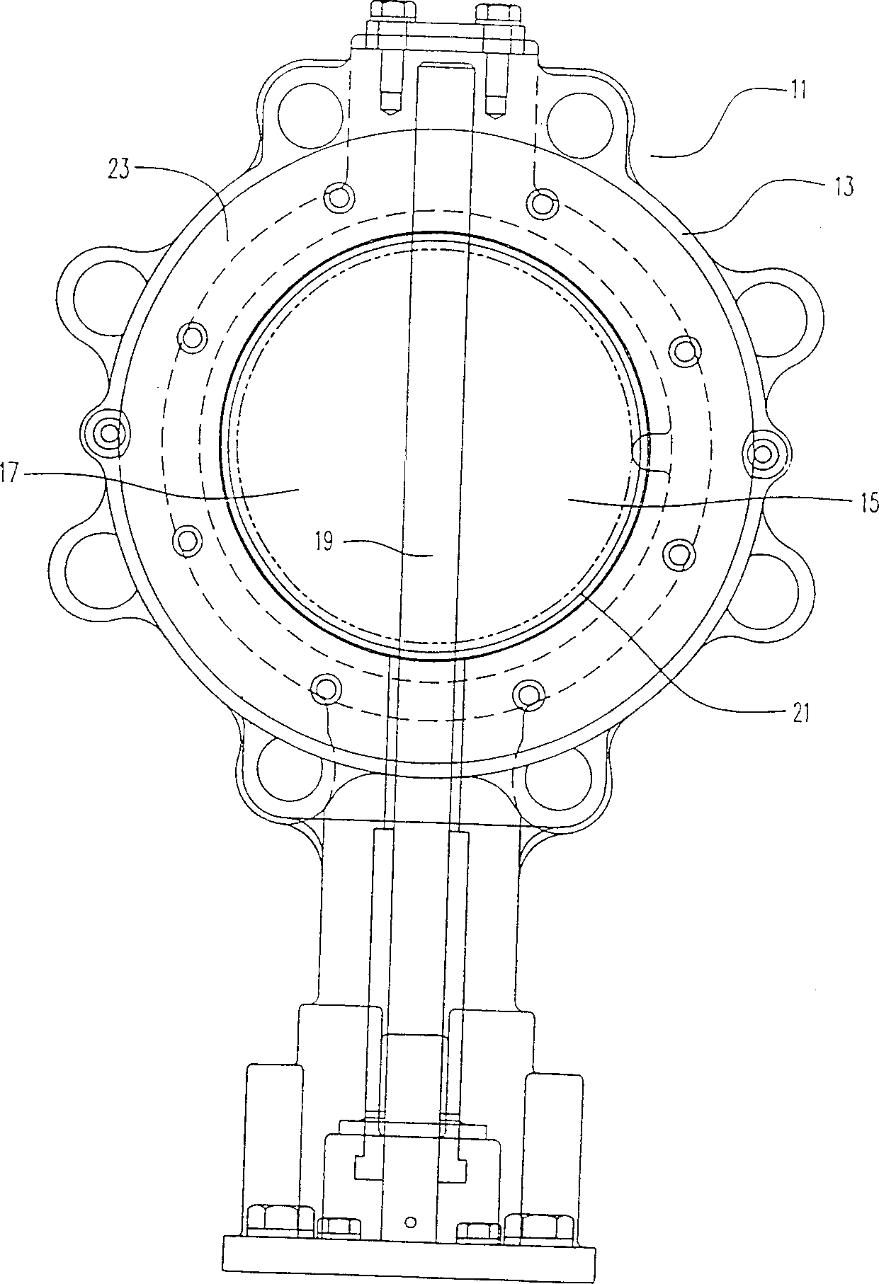
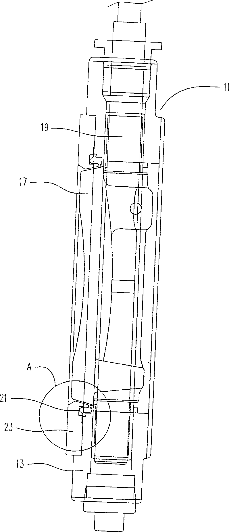
[0026] Such as figure 2 with 3 As shown, the butterfly valve 1 as a preferred embodiment includes a valve body 13 having a central pipe hole 15 through which gaseous or liquid fluid can pass. The spherical valve disc 17 is mounted on the shaft 19 so that it is at least partially located in the hole 15. The valve disc 17 is not a sphere; the term "spherical shape" is used in valve technology to refer to a valve disc 17 that is shaped like a segment or part of a sphere. In this way, its outer edge can form a sphere in space. This can be from Figure 7-9 Clearly seen in. Such as Figure 7 with 8 As shown, the center line of the sphere is located at the center of the shaft and the center of the valve disc from top to bottom. The radius of the sphere R is the radius of the sphere and the radius of the sealing surface ( Figure 7-9 The valve body is not shown). Therefore, generally speaking, the outer circumference of one circular disc surface is larger than the outer circumference of t...


PUM


Abstract

A valve (1) having: a valve body (13) with a centrally located hole (15), an annular groove (27) arranged around the periphery of the hole and a moment arm (25) positioned between the annular groove and the hole ; a rotatable valve shaft (9); a valve disc (17) having a convex outer rim disposed around the periphery of the valve disc; an annular seat (21) having a curved configuration. a first end portion and a second end portion, wherein the first end portion has a concave surface in substantially full contact with the adjacent convex outer edge of the valve body when the valve disc is in the closed position within the bore; annular A seat retainer (23), having an annular groove, also has a moment arm positioned between the annular groove and the hole of the retainer.

Description

Technical field [0001] The present invention relates to a sealing mechanism for valves, mainly butterfly valves. It is used to obtain a tight seal under extreme conditions, and is used to apply pressure, whether in the expected fluid flow direction or in the opposite direction. Prevent leakage when the valve disc is on. This sealing mechanism has an annular seat ring, which has a unique concave surface to engage with the outer convex surface of the valve disc, so as to obtain an extremely tight two-way seal. Background technique [0002] Butterfly valves are used in many industrial applications such as chemical, power, paper, air conditioning, petroleum and refining to control the flow of fluids such as liquids and gases. In addition, this type of valve is used to handle clean, viscous and corrosive liquids; clean and corrosive gases; and water vapor. This type of valve is also used in high temperature applications. This type of valve generally has a valve body with a central hol...

Claims


Application Information

Patent Timeline
IPC IPC(8): F16K1/226F16K1/22
CPCF16K1/2266
Inventor 詹姆斯·E·巴克斯蒂文·K·诺伊拉文·A·劳伦斯
Owner GEN SIGNAL
Why Eureka
Try Eureka